HP Vectra VA 6/xxx HP Vectra VA 6/xxx, User's Guide for Minitower models - Page 26
Refer to HP Summary Screen,
 |
View all HP Vectra VA 6/xxx manuals
Add to My Manuals
Save this manual to your list of manuals |
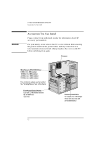
Page 26 highlights
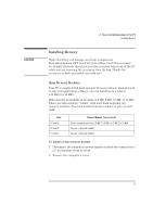
2 How to Install Accessories In Your PC Installing Memory 3 For each memory module, slide it into the slot at 45°. Pivot the memory module to a perpendicular position and click into place. Memory modules have a notch on one side that prevents incorrect insertion. Ensure that you correctly align the notched memory module with the socket. A1 A2 B1 B2 C1 C2 A1 A2 B1 B2 C1 C2 4 If you need to remove a main memory module, release the retaining clip and pull the module forward and out of the socket. 5 Install any other accessories before replacing the cover. Reconnect all cables and power cords. 6 Check the HP Summary Screen to verify the new configuration. Refer to "HP Summary Screen", on page 52. 16 English
-
 1
1 -
2
-
3
-
4
-
5
-
6
-
7
-
8
-
9
-
10
-
11
-
12
-
13
-
14
-
15
-
16
-
17
-
18
-
19
-
20
-
 21
21 -
 22
22 -
 23
23 -
 24
24 -
 25
25 -
 26
26 -
 27
27 -
 28
28 -
 29
29 -
 30
30 -
 31
31 -
32
-
33
-
34
-
35
-
36
-
37
-
38
-
39
-
40
-
41
-
42
-
43
-
44
-
45
-
46
-
47
-
48
-
49
-
50
-
51
-
52
-
53
-
54
-
55
-
56
-
57
-
58
-
59
-
60
-
61
-
62
-
63
-
64
-
65
-
66
-
67
-
68
-
69
-
70
-
71
-
72
-
73
-
74
-
75
-
76
-
77
-
78
-
79
-
80
-
81
-
82
-
83
-
84
-
85
-
86
-
87
-
88
-
89
-
90
-
91
-
92
-
93
-
94
-
95
-
96
 |
 |
2
How to Install Accessories In Your PC
Installing Memory
16
English
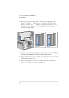
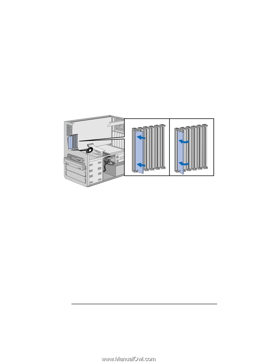
3
For each memory module, slide it into the slot at 45°. Pivot the
memory module to a perpendicular position and click into place.
Memory modules have a notch on one side that prevents incorrect
insertion. Ensure that you correctly align the notched memory
module with the socket.
4
If you need to remove a main memory module, release the retaining
clip and pull the module forward and out of the socket.
5
Install any other accessories before replacing the cover. Reconnect
all cables and power cords.
6
Check the HP Summary Screen to verify the new configuration.
Refer to "HP Summary Screen", on page 52.
A1
B1
C1
A2
B2
C2
A1
B1
C1
A2
B2
C2