HP Vectra XU 6/XXX HP Vectra XU 6/xxx and VT 6/xxx PCs - Technical Reference M - Page 12
System Board - 150
 |
View all HP Vectra XU 6/XXX manuals
Add to My Manuals
Save this manual to your list of manuals |
Page 12 highlights
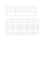
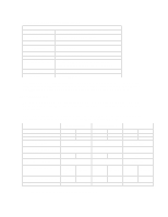
2 SYSTEM BOARD The next chapter describes the video, disk and network devices which are supplied with the PC. This chapter describes the components of the system board. An overview of the system board is first given. Then the components of the Processor-Local Bus, the PCI Bus and the ISA Bus are described in more detail. PRINCIPAL COMPONENTS AND FEATURES The system board contains the following components: PGA ZIF sockets Each processor is packaged in a 387-way pin-grid-array (PGA), which is seated on the system board in a zero-insertion-force (ZIF) socket. The HP Vectra XU 6/xxx PC has two such sockets: the top one is occupied by the Pentium Pro (P6) processor; the bottom one is empty, and can be filled with an optional second Pentium Pro processor. The HP Vectra VT 6/xxx PC has one socket, occupied by the Pentium Pro processor, with no option for fitting a second Pentium Pro processor. VRM sockets The voltage regulator module (VRM) is capable of supplying a voltage of 1.5 V to 3.5 V. This voltage is selected automatically, and depends on the needs of each processor. For instance, the 150 MHz Pentium Pro requires 3.1 V, whilst the 200 MHz version requires 3.3 V. There are two VRM sockets on the HP Vectra XU 6/xxx PC (one of which is already occupied), and one on the HP Vectra VT 6/xxx PC. Accessory Slots There are three accessory slots on the PCI bus, two on the ISA bus, and one that lies on either bus. Thus there are four PCI accessory sockets, and three ISA bus accessory sockets. The top PCI bus slot is already occupied by the Matrox MGA Millennium video controller. On the HP Vectra XU 6/xxx PC, the second PCI slot is also already occupied, by the HP PCI Integrated 10/ 100 VG Interface. (These two boards are described in the next chapter). System Board Switches The first three of the system board switches set the configuration for the PC, as summarized in the table below. The next two set the frequency of the Processor-Local bus, and the last three the ratio of processor-frequency to Processor-Local-bus-frequency. Switch: 1 - CONFG 2 - PSWRD 3 - SECURE 4, 5, 6, 7, 8 Function: Retain or clear the configuration which is stored in EEPROM Enable or clear the User and System Administrator Passwords which are stored in EEPROM Security mode prevents changes to the PC's configuration with the Setup program Processor bus frequencies (see the table on page 15) OFF (default) Retain Enable Disable ON Clear Clear Enable
-
 1
1 -
2
-
3
-
4
-
5
-
6
-
 7
7 -
 8
8 -
 9
9 -
 10
10 -
 11
11 -
 12
12 -
 13
13 -
 14
14 -
 15
15 -
 16
16 -
 17
17 -
18
-
19
-
20
-
21
-
22
-
23
-
24
-
25
-
26
-
27
-
28
-
29
-
30
-
31
-
32
-
33
-
34
-
35
-
36
-
37
-
38
-
39
-
40
-
41
-
42
-
43
-
44
-
45
-
46
-
47
-
48
-
49
-
50
-
51
 |
 |
