| Section |
Page |
| 1 System Overview |
13 |
| Workstation Description |
14 |
| <TABLE> |
14 |
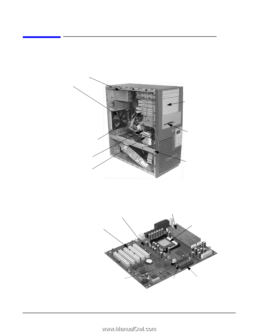
| Internal And External Components |
17 |
| Figure�1�1 Front and Side Views |
17 |
| Figure�1�2 Rear View |
17 |
| Internal Features |
18 |
| <TABLE> |
18 |
| Front Panel |
19 |
| Figure�1�3 Front Panel |
19 |
| Specifications And Characteristics |
20 |
| Physical Characteristics |
20 |
| <TABLE> |
20 |
| Electrical Specifications |
20 |
| <TABLE> |
20 |
| Power Consumption And Cooling |
21 |
| <TABLE> |
21 |
| Environmental Specifications |
22 |
| <TABLE> |
22 |
| Power Saving And Ergonometry |
23 |
| <TABLE> |
23 |
| Power Saving And Ergonometry For APM Systems |
23 |
| <TABLE> |
23 |
| Power Saving Modes And Resume Events For ACPI Systems |
23 |
| <TABLE> |
23 |
| Soft Power Down |
24 |
| Documentation |
25 |
| Access HP World Wide Web Site |
25 |
| Where To Find The Information |
26 |
| 2 System Board |
29 |
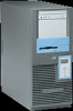
| System Board Description |
30 |
| Figure�2�1 HP Workstation x2100 System Board |
30 |
| Figure�2�2 System Board Chips and Connectors |
31 |
| Architectural View |
32 |
| Accessory Board Slots |
33 |
| Figure�2�3 Accessory Board Slots |
33 |
| Accelerated Graphics Port Slot |
33 |
| Figure�2�4 AGP Slot |
33 |
| Peripheral Component Interconnect Slots |
34 |
| Figure�2�5 PCI Slots |
34 |
| <TABLE> |
34 |
| System Board Switches |
36 |
| <TABLE> |
36 |
| System Chipset |
37 |
| Memory Controller Hub (82850) |
38 |
| Figure�2�6 System Block Diagram using MCH |
38 |
| <TABLE> |
39 |
| MCH Overview |
40 |
| Accelerated Graphics Port (AGP) Bus Interface |
40 |
| Hub Interface |
41 |
| RDRAM Interface |
41 |
| RDRAM Thermal Management |
41 |
| Dual Rambus Bus |
42 |
| RIMM Memory Slots |
42 |
| Figure�2�7 RIMM Memory Slots |
42 |
| Read/Write Buffers |
42 |
| System Clocking |
43 |
| Input/output Controller Hub 2 (82801BA) |
44 |
| Figure�2�8 System Block Diagram Using ICH2 |
44 |
| <TABLE> |
45 |
| ICH2 Features |
46 |
| ICH2 Architecture |
46 |
| ICH2 PCI Bus Interface |
46 |
| SMBus Controller |
46 |
| Low Pin Count Interface |
46 |
| Enhanced USB Controller |
46 |
| AC’97 Controller |
47 |
| IDE Controller |
47 |
| DMA Controller |
47 |
| Interrupt Controller |
47 |
| Timer/Counter Block |
47 |
| Advanced Programmable Interrupt Controller |
48 |
| Real Time Clock |
48 |
| Enhanced Power Management |
48 |
| Crystal CS4299 Integrated PCI Audio |
48 |
| Figure�2�9 CS4280-CS4297 and CS4299 Architecture |
49 |
| Devices On The SMBus |
49 |
| Figure�2�10 Devices on the SMBus |
50 |
| ICH2 SMBus Master Controller |
50 |
| RIMM Sockets |
51 |
| AS98127F |
51 |
| Serial EEPROM |
51 |
| LM75 Temperature Sensor |
51 |
| HP MaxiLife Hardware-monitoring Chip |
51 |
| Figure�2�11 HP MaxiLife Hardware-Monitoring Chip |
51 |
| Test Sequence And Error Messages |
52 |
| MaxiLife Architecture |
53 |
| Figure�2�12 MaxiLife Architecture |
53 |
| Devices On The LPC Bus |
54 |
| Figure�2�13 Devices on the LPC Bus |
54 |
| The Super I/O Controller |
54 |
| <TABLE> |
54 |
| Serial/Parallel Communications Ports |
54 |
| FDC |
55 |
| Keyboard And Mouse Controller |
55 |
| FirmWare Hub (82802AB) |
56 |
| <TABLE> |
56 |
| System Bus |
58 |
| Figure�2�14 The System Bus |
58 |
| Intel Pentium IV Processor |
58 |
| Processor Clock |
59 |
| Bus Frequencies |
59 |
| Voltage Regulation Module (VRM) |
59 |
| Cache Memory |
59 |
| Assigned Device Interrupts |
60 |
| I/o Controller Hub Interrupts |
60 |
| <TABLE> |
60 |
| PCI 64-bit Hub Interrupts |
60 |
| <TABLE> |
60 |
| Interrupt Controllers |
60 |
| PCI IRQ Lines |
62 |
| 3 System BIOS |
63 |
| Overview |
64 |
| Using The HP Setup program |
65 |
| Main Screen |
65 |
| <TABLE> |
65 |
| Advanced Screen |
65 |
| <TABLE> |
65 |
| Processors, Memory And Cache |
66 |
| <TABLE> |
66 |
| Floppy Disk Drives |
66 |
| <TABLE> |
66 |
| IDE Devices |
66 |
| <TABLE> |
66 |
| IDE Primary Master Device |
66 |
| <TABLE> |
66 |
| Integrated USB Interface |
67 |
| <TABLE> |
67 |
| Integrated I/O Ports |
67 |
| <TABLE> |
67 |
| Integrated Audio Device |
67 |
| <TABLE> |
67 |
| AGP Configuration (Video) |
67 |
| <TABLE> |
67 |
| PCI Device, Slot #1 |
67 |
| <TABLE> |
67 |
| Integrated LAN |
68 |
| <TABLE> |
68 |
| Security Screen |
68 |
| <TABLE> |
68 |
| Hardware Protection |
68 |
| <TABLE> |
68 |
| Boot Screen |
69 |
| <TABLE> |
69 |
| Power Screen |
69 |
| <TABLE> |
69 |
| Updating The System BIOS |
70 |
| Figure�3�1 System BIOS Flash Process |
70 |
| Restoring BIOS Default Settings |
70 |
| If You Forget The Administrator Password |
70 |
| Clearing The CMOS |
71 |
| Recovering The BIOS (Crisis Mode) |
71 |
| BIOS Addresses |
73 |
| System Memory Map |
73 |
| HP I/O Port Map (I/O Addresses Used By The System, if configured) |
73 |
| <TABLE> |
74 |
| DMA Channel Controllers |
74 |
| <TABLE> |
75 |
| Interrupt Controllers |
75 |
| <TABLE> |
75 |
| PCI IRQ Lines |
76 |
| 4 Tests And Error Messages |
77 |
| MaxiLife Test Sequence And Error Messages |
78 |
| Basic Pre-boot Diagnostics |
78 |
| Figure�4�1 Possible Error Messages |
79 |
| Figure�4�2 Preboot Diagnostics Error |
79 |
| Pre-boot Diagnostics Error Codes |
80 |
| <TABLE> |
80 |
| POST Sequence And POST Error |
81 |
| Figure�4�3 POST Sequence and POST Error |
81 |
| Figure�4�4 BIOS-generated Errors |
81 |
| Figure�4�5 BIOS-generated Errors |
81 |
| <TABLE> |
81 |
| Operating System Boot Phase |
82 |
| Run-time Errors |
82 |
| <TABLE> |
83 |
| Main Menu |
84 |
| system info |
84 |
| Figure�4�6 System Information |
84 |
| Boot Steps |
85 |
| Figure�4�7 Boot Steps |
85 |
| Boot Report |
85 |
| Order In Which POSTs Occur |
86 |
| <TABLE> |
86 |
| Error Message Summary |
93 |
| <TABLE> |
93 |
| 5 Hardware Components |
97 |
| Graphics Cards |
98 |
| Selecting A Monitor For Your Workstation |
98 |
| <TABLE> |
98 |
| PCI Cards |
100 |
| HP 10/100 TX PCI LAN Interface |
100 |
| HP 10/100 TX PCI LAN Interface Features |
100 |
| <TABLE> |
100 |
| HP 10/100 TX PCI LAN Interface LED Descriptions |
101 |
| <TABLE> |
101 |
| SCSI Adapter Cards |
102 |
| Adaptec 29160 SCSI PCI Adapter Card. |
102 |
| Figure�5�1 Adaptec SCSI Card |
102 |
| SCSI Cable Information |
103 |
| <TABLE> |
103 |
| Additional SCSI Card Features. |
103 |
| <TABLE> |
104 |
| PYRO 1394/Firewire Host Controller Card |
104 |
| Mass Storage Devices |
105 |
| Flexible Disk Drives |
105 |
| Hard Disk Drives |
105 |
| <TABLE> |
105 |
| <TABLE> |
105 |
| <TABLE> |
106 |
| Optical Drives |
106 |
| IDE CD-ROM Drive |
106 |
| <TABLE> |
106 |
| IDE DVD-ROM Drive |
107 |
| <TABLE> |
107 |
| IDE CD-Writer Plus Drive |
107 |
| <TABLE> |
107 |
| Connectors And Sockets |
109 |
| IDE Drive Connectors |
109 |
| <TABLE> |
109 |
| Battery Pinouts |
109 |
| <TABLE> |
109 |
| Additional SCSI LED Connector |
109 |
| <TABLE> |
109 |
| Power Supply Connector (20-pin) And Aux Power Connector |
110 |
| <TABLE> |
110 |
| Wake On LAN Connector |
110 |
| <TABLE> |
110 |
| Rear Fan Connector |
110 |
| <TABLE> |
110 |
| PCI Fan Connector (MT�only) |
110 |
| <TABLE> |
110 |
| internal audio connectors |
110 |
| <TABLE> |
110 |
| Status Panel And Intrusion |
111 |
| <TABLE> |
111 |
| Hard Disk Drive Temperature |
111 |
| <TABLE> |
111 |
| VGA DB15 Connector |
111 |
| <TABLE> |
111 |
| LCD Panel |
112 |
| <TABLE> |
112 |
| Figure�5�2 S-Video Connector |
112 |
| Figure�5�3 Ethernet UTP Connector |
112 |
| Rear Panel Connectors |
113 |
| Figure�5�4 Rear Panel Socket Pin Layouts |
113 |
| Keyboard And Mouse Connectors |
113 |
| <TABLE> |
113 |
| USB Stacked Connector |
114 |
| <TABLE> |
114 |
| Serial Port Connectors |
114 |
| <TABLE> |
114 |
| 25-pin Parallel Connector |
115 |
| <TABLE> |
115 |
| MIDI/Joystick Connector |
116 |
| <TABLE> |
116 |
| External Audio Jacks |
116 |
| 6 Installing Or Replacing Parts And Accessories |
117 |
| Overview |
118 |
| Figure�6�1 Workstation |
118 |
| Figure�6�2 HP Workstation x2100 System Board |
118 |
| Removing And Replacing The Cover And Front�Bezel |
119 |
| Removing The Cover |
119 |
| Removing The Front Bezel |
120 |
| Figure�6�4 Removing the Bezels |
120 |
| Replacing The Cover And Front Bezel |
120 |
| Removing, Replacing And Upgrading Memory |
121 |
| Figure�6�5 Memory Sockets |
121 |
| Removing And Replacing A Memory Module |
121 |
| Installing Or Replacing An Accessory Card |
123 |
| Figure�6�6 Retainer Clip on the Chassis Beam Assembly |
124 |
| Mass Storage And Optical Device Overview |
125 |
| Identifying Cables And Connectors (All Models) |
125 |
| Figure�6�7 Data Cables and Connectors |
125 |
| Installing IDE Drives |
125 |
| <TABLE> |
126 |
| Verifying Your IDE Drive |
126 |
| Installing SCSI Drives |
127 |
| Figure�6�8 Cables and Connectors (SCSI Models) |
127 |
| Setting SCSI IDs |
128 |
| <TABLE> |
128 |
| Which Pins To Jumper |
128 |
| Figure�6�9 Drive Style A |
129 |
| Figure�6�10 Drive Style B |
129 |
| Figure�6�11 Drive Style C |
130 |
| Figure�6�12 Drive Style D |
130 |
| <TABLE> |
130 |
| Verifying Your SCSI Drive |
131 |
| <TABLE> |
131 |
| additional guide rails |
131 |
| Removing And Replacing A Hard Disk Drive |
133 |
| Removing The Old Drive |
133 |
| Figure�6�13 Disconnecting and Removing the Drive |
133 |
| Installing The New Drive |
133 |
| Installing A Second Hard Disk Drive In An Internal Shelf |
135 |
| Installing A Device In A Front Access Bay |
136 |
| Figure�6�14 Attaching the Rails and Installing the Drive |
136 |
| Figure�6�15 Removing the Plastic Filler |
137 |
| Completing Mass Storage Device Installation |
138 |
| IDE Drive |
138 |
| SCSI Drive On SCSI Models |
138 |
| <TABLE> |
138 |
| Replacing The CD-ROM Drive (or DVD-drive) |
139 |
| Removing The Old Drive |
139 |
| Figure�6�16 Removing the Old Drive |
139 |
| iNstalling The New Drive |
139 |
| completing the installation |
139 |
| Replacing The Floppy Disk Drive |
141 |
| Removing The Floppy Disk Drive |
141 |
| Figure�6�17 Removing the Floppy Disk Drive |
141 |
| Installing The Floppy Disk Drive |
141 |
| completing the installation |
141 |
| Replacing The Power Supply Unit |
142 |
| Removing The Power Supply Unit |
142 |
| Figure�6�18 Removing the Power Supply Unit |
142 |
| Installing The Power Supply Unit |
142 |
| Replacing The Processor |
143 |
| Removing The Existing Processor |
143 |
| Figure�6�19 Removing the Processor |
143 |
| Installing The New Processor |
144 |
| Figure�6�20 Inserting the Processor |
144 |
| Figure�6�21 Attaching the Heatsink |
144 |
| Replacing The System Board |
145 |
| Removing The System Board |
145 |
| Figure�6�22 Removing the System Board |
145 |
| installing the new system board |
145 |
| Figure�6�23 Installing the New System Board |
146 |
| Setting System Board Switches |
147 |
| Replacing The System Fan |
148 |
| Removing The Fan |
148 |
| Figure�6�25 Removing the Fan |
148 |
| Replacing The Rear Fan |
149 |
| Replacing The Fan And Speaker Assembly |
150 |
| Removing The Fan And Speaker Assembly |
150 |
| Replacing The Fan And Speaker Assembly |
150 |
| Replacing The Battery |
151 |
| Figure�6�26 Replacing the Battery |
151 |
| System Board Connectors |
152 |
| 7 Troubleshooting Your Workstation |
153 |
| <TABLE> |
154 |
| <TABLE> |
154 |
| <TABLE> |
155 |
| Case 1: No Activity At All |
156 |
| <TABLE> |
156 |
| Case 2: Monitor Is Blank, MaxiLife Is OK |
158 |
| <TABLE> |
158 |
| Case 3: Boot Fails, Monitor Is Blank, MaxiLife Displays Error Message |
160 |
| Pre-boot Diagnostics |
160 |
| Pre-boot Test Errors |
161 |
| <TABLE> |
161 |
| If You Miss The Beep Code |
162 |
| Post Test Errors |
162 |
| <TABLE> |
162 |
| Case 4: Boot Process Fails, Error Message Appears |
164 |
| Error Message Utility (EMU) |
164 |
| <TABLE> |
165 |
| <TABLE> |
165 |
| Case 5: Screen Goes Blank Or Corrupt Image |
166 |
| <TABLE> |
166 |
| Use Or Configuration Problems |
167 |
| <TABLE> |
167 |
| <TABLE> |
167 |
| CMOS Test Error |
168 |
| <TABLE> |
168 |
| Keyboard Test Error |
168 |
| <TABLE> |
168 |
| Floppy Disk Drive Test Error |
169 |
| <TABLE> |
169 |
| hard disk, DVD, CD-RW or CD-ROM test error |
169 |
| <TABLE> |
170 |
| Serial Or Parallel Port Test Error |
171 |
| <TABLE> |
171 |
| Error Message Appears On The MaxiLife LCD During Runtime |
171 |
| <TABLE> |
171 |
| You Cannot Turn Off Your Workstation |
172 |
| <TABLE> |
172 |
| You Have Forgotten Your Password |
173 |
| <TABLE> |
173 |
| Your Workstation Has A Software Problem |
174 |
| <TABLE> |
174 |
| Workstation Clock Does Not Keep Time Correctly |
174 |
| You Have Problems Using The Euro Symbol |
175 |
| For Windows NT Users |
175 |
| Configuring Your Keyboard |
175 |
| Troubleshooting BIOS Problems |
176 |
| Updating The BIOS |
176 |
| Restoring BIOS Default Settings |
176 |
| Clearing The CMOS |
176 |
| Recovering The BIOS (crisis mode) |
177 |
| System Board Switches |
178 |
| Figure�7�1 System Board Switches |
178 |
| Using The HP Setup Program |
179 |
| First, Turn On Or Restart Your Workstation |
179 |
| To Go To The Setup Program |
179 |
| More Troubleshooting For Drives |
180 |
| If The Hard Disk Has A Problem |
180 |
| If The Hard Disk Activity Light Does Not Work |
180 |
| CD-ROM, DVD or CD-RW Drive Does Not Work |
180 |
| CD-ROM, DVD or CD-RW Drive Is Idle |
181 |
| DVD drive doesn’t play DVD video |
181 |
| CD-ROM, DVD or CD-RW Door Does Not Open |
181 |
| HP e-DiagTools Hardware Diagnostics |
182 |
| Overview Of e-DiagTools |
182 |
| running e-DiagTools from the utility partition on your hard disk |
182 |
| Running e-DiagTools From A CD-ROM |
183 |
| Prerequisites |
183 |
| Running e-DiagTools From The Recovery CD |
184 |
| Running e-DiagTools From The Drivers And HP DiagTools CD-ROM |
184 |
| HP e-DiagTools Hardware Tests |
184 |
| for more information |
184 |
| Recovering Hard Disk Drive Contents (Windows only) |
186 |
| Overview |
186 |
| What Functions Are Available? |
186 |
| General Instructions |
186 |
| Recovery Process |
186 |
| Recovering Preloaded Drivers |
187 |
| Changing The Hard Disk |
187 |
| Other Sources Of Information |
188 |
| Online Support For Troubleshooting |
188 |
| Documentation Set Overview |
188 |
| Hewlett-Packard Support And Information Services |
189 |
| collecting information before contacting hp support |
189 |
| <TABLE> |
189 |
| A x2100 Service Information |
191 |
| Parts and Part Numbers |
192 |
| <TABLE> |
193 |
| <TABLE> |
195 |
| <TABLE> |
195 |
 1
1 113
113 114
114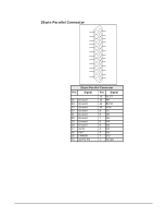 115
115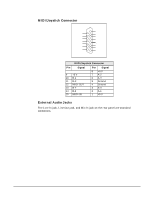 116
116 117
117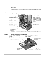 118
118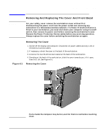 119
119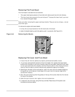 120
120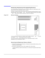 121
121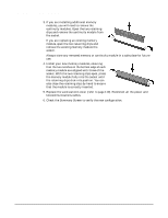 122
122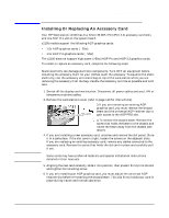 123
123