HP Workstation xw6000 hp workstations xw6000 - hardware reference guide (30115
HP Workstation xw6000 Manual
 |
View all HP Workstation xw6000 manuals
Add to My Manuals
Save this manual to your list of manuals |
HP Workstation xw6000 manual content summary:
- HP Workstation xw6000 | hp workstations xw6000 - hardware reference guide (30115 - Page 1
addendum to the hp workstation xw6000 hardware reference guide The information in this document, where applicable, supersedes specific contents of the hp workstation xw6000 hardware reference guide that is included with your system on the Documentation Library CD. This document includes information - HP Workstation xw6000 | hp workstations xw6000 - hardware reference guide (30115 - Page 2
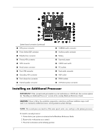
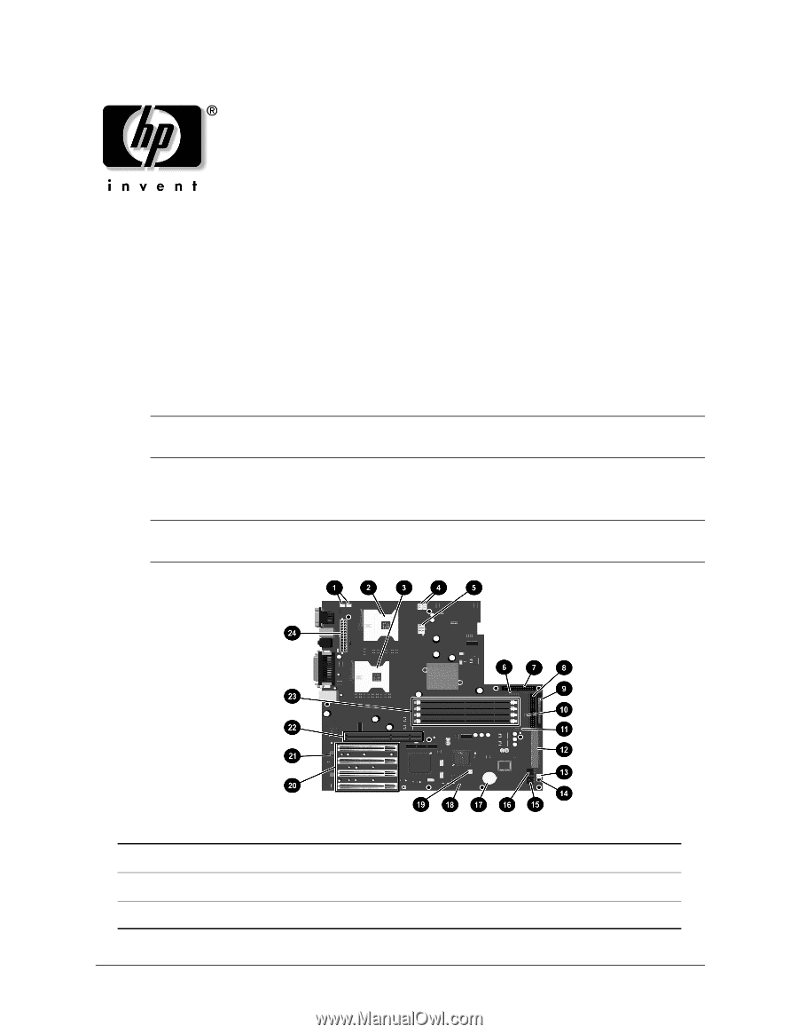
) 5 CPU power connector 6 Power button/LED connector 7 Diskette drive connector 8 Primary ATA connector 9 SCSI connector - Hood sensor connector q Front USB connector w Secondary ATA connector e Front chassis fan connector r Internal speaker connector t CD-ROM audio connector y Auxiliary audio - HP Workstation xw6000 | hp workstations xw6000 - hardware reference guide (30115 - Page 3
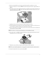
4. Remove any preinstalled screws from the system board around the second processor socket. 5. Open the second processor socket lever 1 fully (the full swing angle of the lever is approximately 135 degrees). 6. Line up the two keyed corners of the pins on the processor with the two keyed corners of - HP Workstation xw6000 | hp workstations xw6000 - hardware reference guide (30115 - Page 4
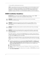
upgrading, or replacing PC2100 DDR SDRAM memory modules in the hp workstation xw6000, care must be taken to avoid incorrect pairing of modules in the same channel. This system does not support Guide for the location of the DIMM sockets. ■ For proper system operation, if your system supports DDR - HP Workstation xw6000 | hp workstations xw6000 - hardware reference guide (30115 - Page 5
a dual-DIMM (dual-channel) of matching sizes, configuration provides. ■ No other memory configurations are supported. Attempts to install memory in of the module type and capacity. Table 1 - Available Memory Configurations for the xw6000 Channel A Channel B Module Total Slot XMM1 Slot XMM3 - HP Workstation xw6000 | hp workstations xw6000 - hardware reference guide (30115 - Page 6
Intel Web site at www.intel.com. 350070-001 6 © 2003 Hewlett-Packard Development Company, L.P. The HP Invent logo is a registered trademark of Hewlett-Packard Development Company, L.P. Microsoft and Windows are U.S. registered trademarks of Microsoft Corporation. Intel is a registered trademark - HP Workstation xw6000 | hp workstations xw6000 - hardware reference guide (30115 - Page 7
hardware reference guide workstation xw6000 Document Part Number: 301155-001 October 2002 This guide is provided as a reference tool. The topics contained herein describe specific features and will assist you with installing additional components such as hard drives, memory, expansion boards, and - HP Workstation xw6000 | hp workstations xw6000 - hardware reference guide (30115 - Page 8
© 2002 Hewlett-Packard Company HP and the HP logo are trademarks of the Hewlett-Packard Company. Microsoft and Windows are trademarks of Microsoft Corporation in the U.S. and/or other countries. All other product names mentioned herein may be trademarks of their respective companies. Hewlett-Packard - HP Workstation xw6000 | hp workstations xw6000 - hardware reference guide (30115 - Page 9
from a Minitower to a Desktop Configuration 1-10 Changing from a Desktop to a Minitower Configuration 1-14 2 Hardware Upgrades Installation Sequence 2-1 Removing the Workstation Access Panel 2-3 Removing the Front Bezel 2-4 Installing Additional Memory 2-5 DIMM Socket Locations 2-5 DIMM - HP Workstation xw6000 | hp workstations xw6000 - hardware reference guide (30115 - Page 10
35 A Specifications B Hard Drive Installation Using the Cable-Select Feature with Ultra ATA Devices B-1 Guidelines for Installing Ultra ATA Devices B-2 SCSI Devices B-3 Guidelines for Using SCSI Devices B-3 Guidelines for Installing SCSI Devices B-5 SCSI Controllers B-5 SCSI Cables B-6 Using - HP Workstation xw6000 | hp workstations xw6000 - hardware reference guide (30115 - Page 11
D Security Lock Provisions Securing the Workstation D-1 E Electrostatic Discharge Preventing Electrostatic Damage E-1 Grounding Methods E-2 F Routine Computer Care and Shipping Preparation Routine Computer Care F-1 CD-ROM Drive Precautions F-2 Operation F-2 Cleaning F-2 Safety F-2 Shipping - HP Workstation xw6000 | hp workstations xw6000 - hardware reference guide (30115 - Page 12
a desktop. Features may vary depending on your model. For a complete listing of the hardware and software installed in your workstation, run Diagnostics for Windows or the INSPECT utility (available on some models). Instructions for using these utilities are provided in the Troubleshooting Guide on - HP Workstation xw6000 | hp workstations xw6000 - hardware reference guide (30115 - Page 13
eject button 2 Dual-state power button 8 CD-ROM drive busy indicator 3 Power-on light 9 Diskette drive eject button 4 Headphone connector - Hard drive activity light 5 1394 connector (optional)* q Microphone connector 6 Universal Serial Bus (USB) connectors *Your workstation is equipped - HP Workstation xw6000 | hp workstations xw6000 - hardware reference guide (30115 - Page 14
panel components 1 Power cord connector 2 Serial connector (Serial A) 3 Serial connector (Serial B) 4 Keyboard connector 5 Headphone/Line-out connector 6 SCSI connector 7 Universal Serial Bus (USB) connectors 8 Mouse connector 9 Microphone/Line-in connector - Parallel connector q Network Interface - HP Workstation xw6000 | hp workstations xw6000 - hardware reference guide (30115 - Page 15
Rear system fan connectors w Secondary ATA connector 5 CPU power connector e Front chassis fan connector 6 Power button header r Internal speaker connector 7 Diskette drive connector t CD-ROM audio connector 8 Primary ATA connector y Auxiliary audio connector 1-4 Hardware Reference Guide - HP Workstation xw6000 | hp workstations xw6000 - hardware reference guide (30115 - Page 16
System Board Components (Continued) Product Features System board components u Battery a Front audio connector i Password header s AGP Pro socket o CMOS reset switch d Secondary Processor Voltage Regulator Module (VRM) p Four PCI slots f Four DIMM sockets Hardware Reference Guide 1-5 - HP Workstation xw6000 | hp workstations xw6000 - hardware reference guide (30115 - Page 17
Product Features Audio System Your workstation has an integrated audio solution that supports analog manually switch the audio signal from analog to digital. See "Solving Audio Problems" in the Troubleshooting Guide on the Documentation Library CD for instructions on how to manually switch the audio - HP Workstation xw6000 | hp workstations xw6000 - hardware reference guide (30115 - Page 18
Keyboard Your workstation ships with software you are using. 2 Windows Logo Key Used in combination with other keys to perform other functions (see "Windows Logo Key" later in this section sites, applications, and services. *Available only in selected geographic regions. Hardware Reference - HP Workstation xw6000 | hp workstations xw6000 - hardware reference guide (30115 - Page 19
service of your choice or to any Web site (URL). Reprogramming the Easy Access Buttons The Easy Access Keyboard icon is located on the Windows desktop status bar. Refer to the Readme-user.txt file for instructions privileges, which require control of the Easy Access Button destinations, - HP Workstation xw6000 | hp workstations xw6000 - hardware reference guide (30115 - Page 20
My Computer Windows Logo Key + F Launches Find Document Windows Logo Key + Ctrl + F Launches Find Computer Windows Logo Key + M Minimizes all open applications Shift + Windows Logo Key + M Undoes Minimize All Windows Logo Key + R Displays the Run dialog box Hardware Reference Guide 1-9 - HP Workstation xw6000 | hp workstations xw6000 - hardware reference guide (30115 - Page 21
the system. 3. Remove the workstation access panel. See "Removing the Workstation Access Panel" in Chapter 2. 4. Remove the front bezel. See "Removing the Front Bezel" in Chapter 2. 5. Disconnect all power and data cables from the drives in the 5.25-inch drive bays. 1-10 Hardware Reference Guide - HP Workstation xw6000 | hp workstations xw6000 - hardware reference guide (30115 - Page 22
the drive casing, gently pull the drive out. Ä CAUTION: When removing a drive, do not pull the drive from the front of the drive bay. To prevent damage to the drive bezel, push the drive and drive casing from the rear for removal from the front of the drive bay. Hardware Reference Guide 1-11 - HP Workstation xw6000 | hp workstations xw6000 - hardware reference guide (30115 - Page 23
Product Features 8. After placing the workstation in the desktop position, gently slide the drives back into the bay. Installing the drives Ä CAUTION: The use of unnecessary force when installing the drive may result in damage to the drive. ✎ In the desktop configuration, always place the diskette - HP Workstation xw6000 | hp workstations xw6000 - hardware reference guide (30115 - Page 24
orientation, use the replacement subpanel that was shipped with your workstation to ensure that the HP logo is properly oriented. 11. Replace the subpanel, front bezel, and the workstation access panel. Be sure that the subpanel and front bezel align properly with the alignment tabs. 12. Reconnect - HP Workstation xw6000 | hp workstations xw6000 - hardware reference guide (30115 - Page 25
the system. 3. Remove the workstation access panel. See "Removing the Workstation Access Panel" in Chapter 2. 4. Remove the front bezel. See "Removing the Front Bezel" in Chapter 2. 5. Disconnect all power and data cables from the drives in the 5.25-inch drive bays. 1-14 Hardware Reference Guide - HP Workstation xw6000 | hp workstations xw6000 - hardware reference guide (30115 - Page 26
the drive casing, gently pull the drives out. Ä CAUTION: When removing a drive, do not pull the drive from the front of the drive bay. To prevent damage to the drive bezel, push the drive and drive casing from the rear for removal from the front of the drive bay. Hardware Reference Guide 1-15 - HP Workstation xw6000 | hp workstations xw6000 - hardware reference guide (30115 - Page 27
diskette drive in the third bay from the top of the chassis to ensure proper drive clearance within the chassis. When all the drives are properly inserted, the drivelock will secure the drives in place. 10. Reconnect the power and data cables to the drives as labeled. 1-16 Hardware Reference Guide - HP Workstation xw6000 | hp workstations xw6000 - hardware reference guide (30115 - Page 28
orientation, use the replacement subpanel that is shipped with your workstation to ensure that the HP logo is properly oriented. 12. Replace the subpanel, front bezel, and the workstation access panel. Be sure that the subpanel and front bezel align properly with the alignment tabs. 13. Reconnect - HP Workstation xw6000 | hp workstations xw6000 - hardware reference guide (30115 - Page 29
Upgrades This chapter explains how to remove the workstation access panel and the front bezel. It also explains how to install the following hardware components: ■ Memory ■ Drives /telephone connectors into the network interface controller (NIC) receptacles. Hardware Reference Guide 2-1 - HP Workstation xw6000 | hp workstations xw6000 - hardware reference guide (30115 - Page 30
panel. See "Removing the Workstation Access Panel" in this chapter. 4. If you are installing or removing drives in the front bays, see "Removing the Front Bezel" in this chapter for instructions. 5. Install any optional equipment, such as memory, additional drives, expansion boards, processors, or - HP Workstation xw6000 | hp workstations xw6000 - hardware reference guide (30115 - Page 31
Upgrades Removing the Workstation Access Panel To remove the workstation access panel: 1. Shut down the operating system properly, then turn off the workstation Loosening the two thumbscrews and removing the workstation access panel ✎ When replacing the workstation access panel, be sure to tighten - HP Workstation xw6000 | hp workstations xw6000 - hardware reference guide (30115 - Page 32
Hardware Upgrades Removing the Front Bezel To remove the front bezel: 1. Shut down the operating system properly, then turn off the workstation and any external devices. 2. Disconnect the power cord from the grounded AC outlet. 3. Remove the workstation access panel. See "Removing the Workstation - HP Workstation xw6000 | hp workstations xw6000 - hardware reference guide (30115 - Page 33
Upgrades Installing Additional Memory Your workstation comes with Double Data Rate-Synchronous dynamic random access memory (DDR-SDRAM) dual inline memory modules (DIMMs). The memory DIMMs in the two unpopulated memory sockets. DIMM Socket Locations Your workstation supports a total of four DIMM - HP Workstation xw6000 | hp workstations xw6000 - hardware reference guide (30115 - Page 34
Upgrades Static electricity can damage the electronic components of the workstation or option boards. Before beginning these procedures, ensure identical type and speed into the unpopulated memory sockets. ■ For proper system operation, if your system supports DDR-SDRAM DIMMs, the DIMMs must Guide - HP Workstation xw6000 | hp workstations xw6000 - hardware reference guide (30115 - Page 35
Hardware Upgrades ■ Install DIMMs in pairs across both memory channels. Each DIMM memory speeds. Performance will reflect the slowest speed DIMM. ■ Use only DIMMs that have been tested and approved by HP. Not all DIMMs meet the HP standard for quality and reliability. Ä CAUTION: Your workstation - HP Workstation xw6000 | hp workstations xw6000 - hardware reference guide (30115 - Page 36
guidelines or your system will not function. 4. Refer to the following illustrations to install memory modules. Installing a DIMM 5. Reassemble the workstation. Removing DIMMs To remove a memory module from a DIMM socket, reverse the procedures in the previous section. 2-8 Hardware Reference - HP Workstation xw6000 | hp workstations xw6000 - hardware reference guide (30115 - Page 37
Hardware Upgrades Installing Additional Drives This section provides a description of the drive bay components. Instructions for removing a bezel blank and how to install or remove a drive are also included. Drive Bay Components Your workstation supports up to five drive bays. Drive bays 1 through 3 - HP Workstation xw6000 | hp workstations xw6000 - hardware reference guide (30115 - Page 38
Hardware Upgrades Minitower Drive Bay Positions ✎ Drive bay numbers are stamped on the chassis behind the front bezel. 2-10 Identifying minitower drive bay components Minitower Drive Bay Components Bay 1 2 3 4 5 Drive Component 5.25-inch, half-height bay for optional drive. 5.25-inch, half- - HP Workstation xw6000 | hp workstations xw6000 - hardware reference guide (30115 - Page 39
Desktop Drive Bay Positions Hardware Upgrades Identifying desktop drive bay components Drive Bay Components No. Bay Drive Component 1 5 3.5-inch, one-third height bay for hard drive. 2 4 3.5-inch, one-third height bay for hard drive. 3 3 3.5-inch, diskette drive mounted in the 5.25-inch, one-third - HP Workstation xw6000 | hp workstations xw6000 - hardware reference guide (30115 - Page 40
and any external devices. 2. Disconnect the power cord from the grounded AC outlet. 3. Remove the workstation access panel. See "Removing the Workstation Access Panel" in this chapter. 4. Remove the front bezel. See "Removing the Front Bezel" in this chapter. 2-12 Hardware Reference Guide - HP Workstation xw6000 | hp workstations xw6000 - hardware reference guide (30115 - Page 41
subpanel ✎ When replacing the subpanel, ensure that the aligning pins are properly oriented. When converting from a minitower to a desktop orientation, use the replacement subpanel that is shipped with your workstation to ensure that the HP logo is properly oriented. Hardware Reference Guide 2-13 - HP Workstation xw6000 | hp workstations xw6000 - hardware reference guide (30115 - Page 42
HP supplied metric screws are black. Identifying the guide screws Installing a Hard Drive The following sections provide instructions for installing a hard drive into a 3.5-inch drive bay and into a 5.25-inch drive bay. Installing a Hard Drive into a 3.5-Inch Drive Bay ✎ Prior to installing a SCSI - HP Workstation xw6000 | hp workstations xw6000 - hardware reference guide (30115 - Page 43
Hardware Upgrades To install a hard drive into a 3.5-inch bay, see the following two illustrations. Installing a hard drive into a 3.5-inch hard drive bay Connecting the signal cable and power cable Hardware Reference Guide 2-15 - HP Workstation xw6000 | hp workstations xw6000 - hardware reference guide (30115 - Page 44
Hardware Upgrades 4. Connect the ends of the cables to the appropriate system board connectors. To locate the appropriate drive connectors, see "System Board Components" in Chapter 1. 5. Reassemble the workstation. Installing a Hard Drive into a 5.25-Inch Drive Bay To install a 3.5-inch hard drive - HP Workstation xw6000 | hp workstations xw6000 - hardware reference guide (30115 - Page 45
Hardware Upgrades 4. Remove four of the guide screws from behind the front bezel on the workstation chassis. See "Locating the Hardware Screws" in this chapter. 5. Secure the drive to the hard drive adapter by installing the four guide screws into the drive as shown in the following illustration. - HP Workstation xw6000 | hp workstations xw6000 - hardware reference guide (30115 - Page 46
Hardware Upgrades 6. Install the adapter in the drive bay by sliding it into the front of the drive cage. The drivelock automatically secures . To locate the appropriate drive connectors, see "System Board Components" in Chapter 1. 8. Reassemble the workstation. 2-18 Hardware Reference Guide - HP Workstation xw6000 | hp workstations xw6000 - hardware reference guide (30115 - Page 47
Upgrades Removing a Drive ✎ If you are replacing the Ultra ATA hard drive in your workstation with a SCSI hard drive, you will need a multimode LVD SCSI cable option kit. Complete the following steps to remove a drive: 1. Shut down the operating system properly, then turn off the workstation - HP Workstation xw6000 | hp workstations xw6000 - hardware reference guide (30115 - Page 48
Hardware Upgrades 4. Disconnect the drive power and signal cables. If the drive is a CD-ROM drive, disconnect the audio connector. 5. Release the drivelock. ❏ If the drive is in the minitower position, slide the drivelock to release the drive in the drive bay. Releasing a drive with the drivelock - HP Workstation xw6000 | hp workstations xw6000 - hardware reference guide (30115 - Page 49
drivelock, push from the back of the drives until the drive casing can be grasped from the front of the workstation. 7. While holding the drive casing, pull the drives out of the drive bay. 8. Store the drives in antistatic packaging. 9. Reassemble the workstation. Hardware Reference Guide 2-21 - HP Workstation xw6000 | hp workstations xw6000 - hardware reference guide (30115 - Page 50
Hardware Upgrades Installing and Removing an Expansion Board This section provides instructions for installing and removing PCI and AGP expansion boards. Identifying the AGP and PCI Sockets Your workstation contains one Accelerated Graphics Port (AGP) socket and four 32-bit, 33-MHz Peripheral - HP Workstation xw6000 | hp workstations xw6000 - hardware reference guide (30115 - Page 51
Upgrades Installing an Expansion Board To install an expansion board: 1. Shut down the operating system properly, then turn off the workstation and any external devices. Disconnect the power cord from the grounded AC outlet. 2. Remove the workstation access panel. See "Removing the Workstation - HP Workstation xw6000 | hp workstations xw6000 - hardware reference guide (30115 - Page 52
workstation, if necessary. Removing an Expansion Board To remove an expansion board, reverse the steps in the previous section. When reversing these steps: ■ Be sure to store the board in antistatic packaging. ■ Install an expansion slot cover to close the open slot. 2-24 Hardware Reference Guide - HP Workstation xw6000 | hp workstations xw6000 - hardware reference guide (30115 - Page 53
Installing an Additional Processor You can upgrade your workstation to a multiprocessor system. When you install a second processor, board. Have an HP authorized reseller or service provider install the processor. If you plan to install it yourself, read all of the instructions carefully before you - HP Workstation xw6000 | hp workstations xw6000 - hardware reference guide (30115 - Page 54
Hardware Upgrades 4. Remove the air baffle: a. Gently pull up on the air baffle until it comes loose from the fan assembly. b. Lift the air baffle out of the chassis. Removing the air baffle 2-26 Hardware Reference Guide - HP Workstation xw6000 | hp workstations xw6000 - hardware reference guide (30115 - Page 55
Hardware Upgrades 5. Install the second processor (refer to the that processor, be sure to install the processor in the primary processor socket or your workstation will not function. c. Lightly press down on the top of the processor while closing out of the socket. Hardware Reference Guide 2-27 - HP Workstation xw6000 | hp workstations xw6000 - hardware reference guide (30115 - Page 56
Upgrades e. Place the thermal grease on the bottom of the heatsink before setting the heatsink on top of the processor. ✎ Your workstation may come preinstalled with screws around the second processor area where the new heatsink will attach. Remove these screws before installing the new heatsink - HP Workstation xw6000 | hp workstations xw6000 - hardware reference guide (30115 - Page 57
Hardware Upgrades 6. Reinstall the air baffle: a. Carefully lower the air baffle into the chassis over the heatsinks. b. Gently press down on the air baffle until it fits into the fan assembly. Ä CAUTION: The air baffle is essential to proper cooling of the processors. Without it, the processor will - HP Workstation xw6000 | hp workstations xw6000 - hardware reference guide (30115 - Page 58
board. Have an HP authorized reseller or service provider install the processor. If you choose to install it yourself, read all of the instructions carefully before you begin. Ä CAUTION: Static electricity can damage the electronic components of the workstation. Before beginning these procedures - HP Workstation xw6000 | hp workstations xw6000 - hardware reference guide (30115 - Page 59
, contact your authorized service provider to purchase the necessary hardware option kit. This kit contains the following items: ■ Processor ■ Alcohol swab ■ Heatsink with thermal grease Guidelines for Separating the Heatsink/Processor Assembly Before upgrading your workstation with a new processor - HP Workstation xw6000 | hp workstations xw6000 - hardware reference guide (30115 - Page 60
, yet keep the compound pliable that is holding the processor to the heatsink. 1. Turn on the workstation and allow the operating system to boot. 2. Shut down the operating system properly, then turn off the workstation and any external devices. Disconnect the power cord from the grounded AC - HP Workstation xw6000 | hp workstations xw6000 - hardware reference guide (30115 - Page 61
Hardware Upgrades 4. Remove the air baffle: a. Gently pull up on the air baffle until it comes loose from the fan assembly. b. Lift the air baffle out of the chassis. Removing the air baffle 5. Ensure that the heatsink is warm to the touch. Ä CAUTION: Lifting the heatsink straight up while it is in - HP Workstation xw6000 | hp workstations xw6000 - hardware reference guide (30115 - Page 62
Upgrades 6. Remove the heatsink: a. Untighten the captive screws 1. b. Twist the heatsink slightly 2 to break the compound that is holding it to the processor. c. Lift the heatsink off the processor 3. Twisting and lifting the heatsink off the processor Ä CAUTION: Lifting the heatsink the heatsink - HP Workstation xw6000 | hp workstations xw6000 - hardware reference guide (30115 - Page 63
Hardware Upgrades 7. Remove the processor: a. Open the secondary processor socket lever 1 fully (the full swing angle of the lever is approximately a New Processor To install a new processor, see the "Installing an Additional Processor" section in this chapter. Hardware Reference Guide 2-35 - HP Workstation xw6000 | hp workstations xw6000 - hardware reference guide (30115 - Page 64
hp workstation xw6000 Component Minitower Dimensions Height Width Depth Desktop Dimensions Height Width Depth Approximate Weight Nonoperating Power Output Rated Input Current (maximum) Heat Dissipation (maximum) Hardware Reference Guide A Specifications U.S. 17.65 in 6.60 in 17.75 in 6.60 in 17.65 - HP Workstation xw6000 | hp workstations xw6000 - hardware reference guide (30115 - Page 65
Selected models of the HP workstation xw6000 have an internal Ultra ATA hard drive installed. The configuration of the drive employs a cable-select feature that identifies the drive as device 0 (primary drive) or device 1 (secondary drive). Device 1 is the drive connected to the cable's middle - HP Workstation xw6000 | hp workstations xw6000 - hardware reference guide (30115 - Page 66
the secondary controller. ■ Install either a third-height or a half-height drive into a half-height bay. ■ Install guide screws to ensure that the drive lines up correctly in the drive cage. HP has provided extra guide screws installed in the front of the workstation chassis behind the front bezel - HP Workstation xw6000 | hp workstations xw6000 - hardware reference guide (30115 - Page 67
Hard Drive Installation SCSI Devices This section contains information relating to SCSI device guidelines and installation. Guidelines for Using SCSI Devices When installing and operating SCSI devices, you must follow these guidelines: ■ A single Ultra SCSI controller supports up to seven SCSI - HP Workstation xw6000 | hp workstations xw6000 - hardware reference guide (30115 - Page 68
This action enables the SCSI controller to recognize the external devices. ■ The system accommodates a combination of internal and external SCSI devices, such as hard drives, tape drives, and CD-ROM drives. ■ HP does not recommend mixing different-width SCSI devices on the same SCSI chain or on the - HP Workstation xw6000 | hp workstations xw6000 - hardware reference guide (30115 - Page 69
hard drives in the same system, the Ultra ATA drive will be the boot drive unless the boot order is changed in the F10 Setup. When replacing a hard drive, the replacement drive should be of the same type as the drive being removed. If you are replacing an Ultra ATA hard drive with a SCSI hard drive - HP Workstation xw6000 | hp workstations xw6000 - hardware reference guide (30115 - Page 70
Hard Drive Installation SCSI Cables The front drive bays are available for installing or connecting mass storage SCSI devices. Using a SCSI Cable Selected models of the HP workstation xw6000 ship with a multimode SCSI cable that supports Low Voltage Differential (LVD) or single-ended devices. The - HP Workstation xw6000 | hp workstations xw6000 - hardware reference guide (30115 - Page 71
Hard Drive Installation Using SCSISelect with SCSI Devices The SCSI host adapter includes the SCSISelect utility to configure the host adapter and to run SCSI disk utilities. To run the SCSISelect utility: ■ In Post Messages Enabled mode: Press Ctrl + A when the Press for SCSISelect - HP Workstation xw6000 | hp workstations xw6000 - hardware reference guide (30115 - Page 72
battery may be purchased at your local retailer or from the HP Web site. ✎ The spare part number for a standard HP spare designated for this product. Ä CAUTION: Static electricity can damage the electronic components of the workstation HP, your authorized partners, or their agents. Hardware Reference - HP Workstation xw6000 | hp workstations xw6000 - hardware reference guide (30115 - Page 73
disconnect the power cord from the electrical outlet, and remove the computer cover or access panel. ✎ It may be necessary to remove an expansion card to gain access to the battery. 2. Locate the battery 1 and battery holder 2 on the system board, as shown in the following illustration. Battery and - HP Workstation xw6000 | hp workstations xw6000 - hardware reference guide (30115 - Page 74
and turn on the computer. 8. Reset the date and time, your passwords, and any special system setups, using Computer Setup. Refer to the Computer Setup Guide on the Documentation Library CD for additional information. Hardware Reference - HP Workstation xw6000 | hp workstations xw6000 - hardware reference guide (30115 - Page 75
a lock 1 (not provided) to control access to the inside components. Your workstation is also designed with a cable lock slot 2. An optional cable lock is available to help secure the workstation to a fixed object using this cable lock slot. Securing the workstation Hardware Reference Guide D-1 - HP Workstation xw6000 | hp workstations xw6000 - hardware reference guide (30115 - Page 76
transporting and storing products in static-safe containers. ■ Keep electrostatic-sensitive parts in their containers until they arrive at static-free workstations. ■ Place parts on a grounded surface before removing them from their containers. ■ Avoid touching pins, leads, or circuitry. ■ Always be - HP Workstation xw6000 | hp workstations xw6000 - hardware reference guide (30115 - Page 77
field service kit with a folding static-dissipating work mat. ✎ If you do not have any of the suggested equipment for proper grounding or if you need for more information about static electricity, contact your HP authorized dealer, reseller, or service provider. E-2 Hardware Reference Guide - HP Workstation xw6000 | hp workstations xw6000 - hardware reference guide (30115 - Page 78
, with the keyboard feet down, directly against the front of a unit that is in a desktop configuration because this also restricts airflow. ■ Keep the A, "Specifications," in this guide. ■ Keep liquids away from the computer and keyboard. ■ Never cover the ventilation slots on the monitor with any - HP Workstation xw6000 | hp workstations xw6000 - hardware reference guide (30115 - Page 79
, mechanical vibration, or direct sunlight. Cleaning ■ Clean the panel and controls with a soft, dry cloth or a soft cloth lightly moistened with falls into the drive, immediately unplug the computer and have it checked by an authorized HP service provider. F-2 Hardware Reference Guide - HP Workstation xw6000 | hp workstations xw6000 - hardware reference guide (30115 - Page 80
not exposed to electrical or magnetic impulses while stored or in transit. ✎ The hard drive locks automatically when the system power is turned off. 2. Remove and store any program diskettes ✎ For environmental nonoperating ranges, see Appendix A, "Specifications," in this guide. Hardware Reference - HP Workstation xw6000 | hp workstations xw6000 - hardware reference guide (30115 - Page 81
CD-ROM drive, precautions F-2 components drive bay 2-9 front panel 1-2 Hardware Reference Guide Index installation precautions 2-1 installation sequence 2-1 rear panel 1-3 configuration desktop 1-10 minitower 1-14 cool-down time, processor 2-31 customer service 1-10 D desktop configuration changing - HP Workstation xw6000 | hp workstations xw6000 - hardware reference guide (30115 - Page 82
2-22 installation sequence 2-2 removal 2-22 F front bezel proper handling 2-13 removing 2-4 front panel components 1-2 G grounding methods E-2 guide screws 2-14 H hard drive adapter 2-16 installing 2-14, 2-16 removing 2-19 hardware screws 2-14 hardware upgrade kit, processor 2-31 headphone connector - HP Workstation xw6000 | hp workstations xw6000 - hardware reference guide (30115 - Page 83
system board connectors audio 1-4 CD-ROM audio 1-4 diskette drive 1-4 power supply 1-4 primary ATA 1-4 secondary ATA 1-4 system board sockets AGP Pro 1-5 PCI 1-5 primary processor 1-4 secondary processor 1-4 T termination, SCSI chain B-4 TEST utility 2-2 U UATA-100 cable B-2 upgrade kit, processor
-
 1
1 -
 2
2 -
 3
3 -
 4
4 -
 5
5 -
 6
6 -
 7
7 -
8
-
9
-
10
-
11
-
12
-
13
-
14
-
15
-
16
-
17
-
18
-
19
-
20
-
21
-
22
-
23
-
24
-
25
-
26
-
27
-
28
-
29
-
30
-
31
-
32
-
33
-
34
-
35
-
36
-
37
-
38
-
39
-
40
-
41
-
42
-
43
-
44
-
45
-
46
-
47
-
48
-
49
-
50
-
51
-
52
-
53
-
54
-
55
-
56
-
57
-
58
-
59
-
60
-
61
-
62
-
63
-
64
-
65
-
66
-
67
-
68
-
69
-
70
-
71
-
72
-
73
-
74
-
75
-
76
-
77
-
78
-
79
-
80
-
81
-
82
-
83
 |
 |
1
addendum to the hp workstation xw6000
hardware reference guide
The information in this document, where applicable, supersedes specific contents of the
hp workstation
xw6000 hardware reference guide
that is included with your system on the
Documentation Library
CD.
This document includes information about:
■
System board components
■
Installation of a second processor
■
Installation of DIMMs
■
Hyper-Threading Technology
IMPORTANT:
Read this document first before referencing the Hardware Reference Guide included on
the
Documentation Library
CD.
System Board Components
IMPORTANT:
If the system board part number in your workstation is 339100-xxx, this section replaces
the “System Board Components” section of the existing Hardware Reference Guide.
System board connectors
1
Rear chassis fan connectors
3
Secondary processor socket
2
Primary processor socket
4
Processor fan connectors
Continued on next page.