HP dx2040 Service Reference Guide: HP Compaq dx2040 Business PC - Page 44
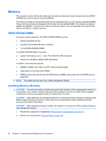
Memory, DDR2-SDRAM DIMMs, Installing Memory Modules
 |
View all HP dx2040 manuals
Add to My Manuals
Save this manual to your list of manuals |
Page 44 highlights
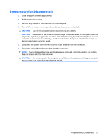
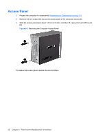
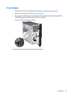
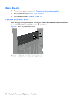
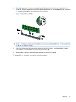
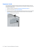
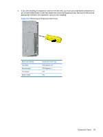
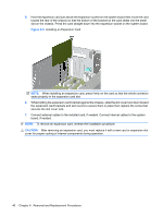
Memory The computer comes with double data rate 2 synchronous dynamic random access memory (DDR2SDRAM) dual inline memory modules (DIMMs). The memory sockets on the system board can be populated with up to two industry-standard DIMMs. These memory sockets are populated with at least one preinstalled DIMM. The sockets are labeled DIMM1 and DIMM2. To achieve the maximum memory support, you can populate the system board with up to 4 GB (2 x 2 GB) of memory. DDR2-SDRAM DIMMs For proper system operation, the DDR2-SDRAM DIMMs must be: ● industry-standard 240-pin ● unbuffered PC2-5300 667 MHz-compliant ● 1.8 volt DDR2-SDRAM DIMMs The DDR2-SDRAM DIMMs must also: ● support CAS latency 4 (CL = 4) for PC2-5300 667 MHz-compliant ● contain the mandatory JEDEC SPD information In addition, the computer supports: ● 256Mbit, 512Mbit, and 1Gbit non-ECC memory technologies ● single-sided and double-sided DIMMs ● DIMMs constructed with x8 and x16 DDR devices; DIMMs constructed with x4 SDRAM are not supported NOTE: The system will not start if you install unsupported DIMMs. Installing Memory Modules CAUTION: The memory module sockets have gold metal contacts. When upgrading the memory, it is important to use memory modules with gold metal contacts to prevent corrosion and/or oxidation resulting from having incompatible metals in contact with each other. CAUTION: Static electricity can damage the electronic components of the computer or optional cards. Before beginning these procedures, ensure that you are discharged of static electricity by briefly touching a grounded metal object. CAUTION: When handling a memory module, be careful not to touch any of the contacts. Doing so may damage the module. 1. Prepare the computer for disassembly (Preparation for Disassembly on page 31). 2. Remove the access panel. (Access Panel on page 32) 36 Chapter 6 Removal and Replacement Procedures
-
 1
1 -
2
-
3
-
4
-
5
-
6
-
7
-
8
-
9
-
10
-
11
-
12
-
13
-
14
-
15
-
16
-
17
-
18
-
19
-
20
-
21
-
22
-
23
-
24
-
25
-
26
-
27
-
28
-
29
-
30
-
31
-
32
-
33
-
34
-
35
-
36
-
37
-
38
-
 39
39 -
 40
40 -
 41
41 -
 42
42 -
 43
43 -
 44
44 -
 45
45 -
 46
46 -
 47
47 -
 48
48 -
 49
49 -
50
-
51
-
52
-
53
-
54
-
55
-
56
-
57
-
58
-
59
-
60
-
61
-
62
-
63
-
64
-
65
-
66
-
67
-
68
-
69
-
70
-
71
-
72
-
73
-
74
-
75
-
76
-
77
-
78
-
79
-
80
-
81
-
82
-
83
-
84
-
85
-
86
-
87
-
88
-
89
 |
 |