HP dx2040 Service Reference Guide: HP Compaq dx2040 Business PC - Page 56
Front I/O Panel Housing Assembly
 |
View all HP dx2040 manuals
Add to My Manuals
Save this manual to your list of manuals |
Page 56 highlights
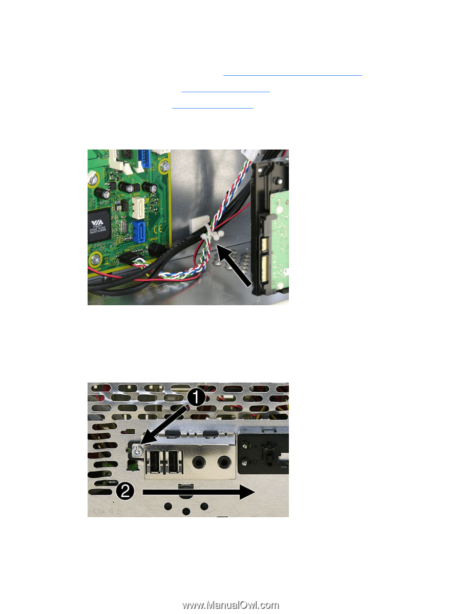
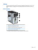
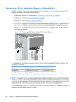
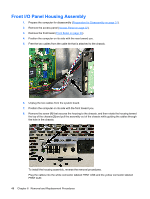
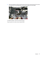
Front I/O Panel Housing Assembly 1. Prepare the computer for disassembly (Preparation for Disassembly on page 31). 2. Remove the access panel (Access Panel on page 32). 3. Remove the front bezel (Front Bezel on page 33). 4. Position the computer on its side with the rear toward you. 5. Free the two cables from the cable tie that is attached to the chassis. 6. Unplug the two cables from the system board. 7. Position the computer on its side with the front toward you. 8. Remove the screw (1) that secures the housing to the chassis, and then rotate the housing toward the top of the chassis (2) and pull the assembly out of the chassis while guiding the cables through the hole in the chassis. To install the housing assembly, reverse the removal procedures. Plug the cables into the white connector labeled FRNT USB and the yellow connector labeled FRNT AUD. 48 Chapter 6 Removal and Replacement Procedures
-
 1
1 -
2
-
3
-
4
-
5
-
6
-
7
-
8
-
9
-
10
-
11
-
12
-
13
-
14
-
15
-
16
-
17
-
18
-
19
-
20
-
21
-
22
-
23
-
24
-
25
-
26
-
27
-
28
-
29
-
30
-
31
-
32
-
33
-
34
-
35
-
36
-
37
-
38
-
39
-
40
-
41
-
42
-
43
-
44
-
45
-
46
-
47
-
48
-
49
-
50
-
 51
51 -
 52
52 -
 53
53 -
 54
54 -
 55
55 -
 56
56 -
 57
57 -
 58
58 -
 59
59 -
 60
60 -
 61
61 -
62
-
63
-
64
-
65
-
66
-
67
-
68
-
69
-
70
-
71
-
72
-
73
-
74
-
75
-
76
-
77
-
78
-
79
-
80
-
81
-
82
-
83
-
84
-
85
-
86
-
87
-
88
-
89
 |
 |