HP dx2718 service reference guide: HP Compaq dx2710 MT/dx2718 MT/dx2710 SFF Bu - Page 39
Front Bezel MT Chassis, Preparation for Disassembly, Access Panel MT Chassis
 |
View all HP dx2718 manuals
Add to My Manuals
Save this manual to your list of manuals |
Page 39 highlights
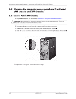
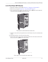
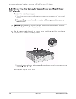
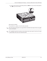
Removal and Replacement Procedures- Microtower (MT)/Small Form Factor (SFF) Chassis 6.2.2 Front Bezel (MT Chassis) 1. Prepare the computer for disassembly (Section 6.1, "Preparation for Disassembly"). 2. Remove the access panel (Section 6.2.1, "Access Panel (MT Chassis)"). 3. Press outward on the three latches on the right side of the bezel 1, then rotate the right side of the bezel off the chassis 2 followed by the left side. * * These apply for selected models and countries only. 4. Continue to rotate the bezel, then push the bezel to the bottom to release the top latches from chassis. To reinstall the front bezel, reverse the removal procedure. 5. Insert the three hooks on the left side of the bezel into the slots on the chassis and rotate the bezel on from left to right 1 so that it snaps in place. * * These apply for selected models and countries only. Service Reference Guide 483941-001 6-3
-
 1
1 -
2
-
3
-
4
-
5
-
6
-
7
-
8
-
9
-
10
-
11
-
12
-
13
-
14
-
15
-
16
-
17
-
18
-
19
-
20
-
21
-
22
-
23
-
24
-
25
-
26
-
27
-
28
-
29
-
30
-
31
-
32
-
33
-
 34
34 -
 35
35 -
 36
36 -
 37
37 -
 38
38 -
 39
39 -
 40
40 -
 41
41 -
 42
42 -
 43
43 -
 44
44 -
45
-
46
-
47
-
48
-
49
-
50
-
51
-
52
-
53
-
54
-
55
-
56
-
57
-
58
-
59
-
60
-
61
-
62
-
63
-
64
-
65
-
66
-
67
-
68
-
69
-
70
-
71
-
72
-
73
-
74
-
75
-
76
-
77
-
78
-
79
-
80
-
81
-
82
-
83
-
84
-
85
-
86
-
87
-
88
-
89
-
90
-
91
-
92
-
93
-
94
-
95
-
96
-
97
-
98
-
99
-
100
-
101
-
102
-
103
-
104
-
105
-
106
-
107
 |
 |
