HP nx6320 Maintenance and Service Guide - Page 167
Serial Connector Module, Serial Connector Module Spare Part Number Information
 |
View all HP nx6320 manuals
Add to My Manuals
Save this manual to your list of manuals |
Page 167 highlights
Removal and Replacement Procedures 5.25 Serial Connector Module Serial Connector Module Spare Part Number Information Serial connector module (includes serial connector module cable) 413694-001 1. Prepare the computer for disassembly (Section 5.3), and then remove the following components: a. Hard drive (Section 5.4) b. Bluetooth module (Section 5.6) c. Optical drive (Section 5.9) d. Keyboard (Section 5.10) e. Switch cover (Section 5.17) f. Fan (Section 5.11) g. Heat sink (Section 5.12) h. RTC battery (Section 5.14) i. Display assembly (Section 5.18) j. Top cover (Section 5.19) k. Speaker (Section 5.20) l. USB/audio board (Section 5.23) Maintenance and Service Guide 5-65
-
 1
1 -
2
-
3
-
4
-
5
-
6
-
7
-
8
-
9
-
10
-
11
-
12
-
13
-
14
-
15
-
16
-
17
-
18
-
19
-
20
-
21
-
22
-
23
-
24
-
25
-
26
-
27
-
28
-
29
-
30
-
31
-
32
-
33
-
34
-
35
-
36
-
37
-
38
-
39
-
40
-
41
-
42
-
43
-
44
-
45
-
46
-
47
-
48
-
49
-
50
-
51
-
52
-
53
-
54
-
55
-
56
-
57
-
58
-
59
-
60
-
61
-
62
-
63
-
64
-
65
-
66
-
67
-
68
-
69
-
70
-
71
-
72
-
73
-
74
-
75
-
76
-
77
-
78
-
79
-
80
-
81
-
82
-
83
-
84
-
85
-
86
-
87
-
88
-
89
-
90
-
91
-
92
-
93
-
94
-
95
-
96
-
97
-
98
-
99
-
100
-
101
-
102
-
103
-
104
-
105
-
106
-
107
-
108
-
109
-
110
-
111
-
112
-
113
-
114
-
115
-
116
-
117
-
118
-
119
-
120
-
121
-
122
-
123
-
124
-
125
-
126
-
127
-
128
-
129
-
130
-
131
-
132
-
133
-
134
-
135
-
136
-
137
-
138
-
139
-
140
-
141
-
142
-
143
-
144
-
145
-
146
-
147
-
148
-
149
-
150
-
151
-
152
-
153
-
154
-
155
-
156
-
157
-
158
-
159
-
160
-
161
-
 162
162 -
 163
163 -
 164
164 -
 165
165 -
 166
166 -
 167
167 -
 168
168 -
 169
169 -
 170
170 -
 171
171 -
 172
172 -
173
-
174
-
175
-
176
-
177
-
178
-
179
-
180
-
181
-
182
-
183
-
184
-
185
-
186
-
187
-
188
-
189
-
190
-
191
-
192
-
193
-
194
-
195
-
196
-
197
-
198
-
199
-
200
-
201
-
202
-
203
-
204
-
205
-
206
-
207
-
208
-
209
-
210
-
211
-
212
-
213
-
214
-
215
-
216
-
217
-
218
-
219
-
220
-
221
-
222
-
223
-
224
-
225
-
226
-
227
-
228
-
229
-
230
-
231
-
232
-
233
-
234
-
235
-
236
-
237
-
238
-
239
-
240
-
241
-
242
-
243
-
244
-
245
-
246
-
247
-
248
-
249
-
250
-
251
-
252
 |
 |

Removal and Replacement Procedures
Maintenance and Service Guide
5–65
5.25
Serial Connector Module
1. Prepare the computer for disassembly (
Section 5.3
),
and then remove the following components:
a.
Hard drive (
Section 5.4
)
b.
Bluetooth module (
Section 5.6
)
c.
Optical drive (
Section 5.9
)
d.
Keyboard (
Section 5.10
)
e.
Switch cover (
Section 5.17
)
f.
Fan (
Section 5.11
)
g.
Heat sink (
Section 5.12
)
h.
RTC battery (
Section 5.14
)
i.
Display assembly (
Section 5.18
)
j.
Top cover (
Section 5.19
)
k.
Speaker (
Section 5.20
)
l.
USB/audio board (
Section 5.23
)
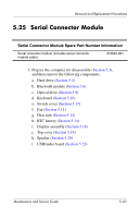
Serial Connector Module Spare Part Number Information
Serial connector module (includes serial connector
module cable)
413694-001