HP vc4825T HP vc4820T/vc4825T Thin Clients Hardware Reference Guide - Page 27
Serial Port Jumper Locations on the System Board, on Serial
 |
View all HP vc4825T manuals
Add to My Manuals
Save this manual to your list of manuals |
Page 27 highlights
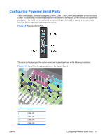
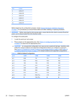
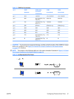
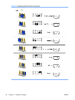
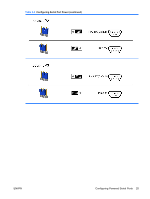
Table 2-2 COM Port Functionality pin # COM1 (Standard) pin 1 pin 2 DCD RXD pin 3 TXD pin 4 pin 5 pin 6 pin 7 pin 8 DTR GND DSR RTS CTS pin 9 RI COM2-Cable Connection (Customized) COM3 (Customized) +5V/DCD +5V/+12V/DCD RXD/TXD/RXD (TTL)/ RXD/TXD TXD (TTL) TXD/RXD/TXD (TTL)/ TXD/RXD RXD (TTL) DTR/+5V DTR/+5V/+12v GND GND DSR DSR RTS RTS RXD/TXD/RXD (TTL)/ CTS TXD (TTL) TXD/RXD/TXD (TTL)/ RI RXD (TTL) COM4 (Customized) +5V/+12V/DCD RXD/TXD TXD/RXD DTR/+5V/+12v GND DSR RTS CTS RI CAUTION: To prevent severe equipment damage, carefully verify the location of the COM Port Jumper before you configure it. See Figure 2-10 Serial Port Jumper Locations on the System Board on page 19 for locations. NOTE: The jumpers in the following table are in the same orientation illustrated in Figure 2-10 Serial Port Jumper Locations on the System Board on page 19. Table 2-3 Configuring Serial Port Power ENWW Configuring Powered Serial Ports 21
-
 1
1 -
2
-
3
-
4
-
5
-
6
-
7
-
8
-
9
-
10
-
11
-
12
-
13
-
14
-
15
-
16
-
17
-
18
-
19
-
20
-
21
-
 22
22 -
 23
23 -
 24
24 -
 25
25 -
 26
26 -
 27
27 -
 28
28 -
 29
29 -
 30
30 -
 31
31 -
 32
32 -
33
-
34
-
35
-
36
-
37
-
38
-
39
-
40
-
41
-
42
-
43
-
44
-
45
-
46
-
47
-
48
 |
 |
