Hitachi 26LD9000TA Owners Guide - Page 10
Component Names
 |
View all Hitachi 26LD9000TA manuals
Add to My Manuals
Save this manual to your list of manuals |
Page 10 highlights
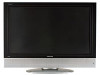
COMPONENT NAMES Main Unit Front Panel 7 6! 1. Cabinet 1 2. Panel 3. Indicating Lamp 2 4. Remote Control Receiver 5. Speaker 6. Desktop Stand 7. Main Power Switch (on the left side) 3! 4 5 Rear Panel 1. Side Input 2. Power Cord Socket 3. Terminal Board (External Device Connection) 4. Control Panel (see below for details) Please refer to 14 ~ 18 for the detailed information for the connections. 26LD9000TA 4 32LD9000TA 4 3 2 1 ! Control Panel These buttons are located on the top. 5, 6 2 3 2 1 ! 1. Sub Power button 2. Menu button 3. Program UP/ S button 4. Program DOWN/ T button 5. Volume UP /f button 6. Volume DOWN /ebutton 7. Input/OK button ! 7 10 3, 4 1
-
 1
1 -
2
-
3
-
4
-
 5
5 -
 6
6 -
 7
7 -
 8
8 -
 9
9 -
 10
10 -
 11
11 -
 12
12 -
 13
13 -
 14
14 -
 15
15 -
16
-
17
-
18
-
19
-
20
-
21
-
22
-
23
-
24
-
25
-
26
-
27
-
28
-
29
-
30
-
31
-
32
-
33
-
34
-
35
-
36
-
37
-
38
-
39
-
40
-
41
 |
 |

10
COMPONENT NAMES
Main Unit
Front Panel
1. Cabinet
2. Panel
3. Indicating Lamp
4. Remote Control Receiver
5. Speaker
6. Desktop Stand
7. Main Power Switch (on the left side)
Rear Panel
1. Side Input
2. Power Cord Socket
3. Terminal Board (External Device Connection)
4. Control Panel (see below for details)
Please refer to
14
~
18
for the detailed information for the connections.
26LD9000TA
32LD9000TA
Control Panel
1. Sub Power button
2. Menu button
3. Program UP/
button
4. Program DOWN/
button
5. Volume UP
/
button
6. Volume DOWN
/
button
7. Input/OK button
1
2
3
7
5
4
6
These buttons are located on the top.
2
1
5, 6
3, 4
7
3
2
1
4
3
2
1
4