Hitachi 42EDT41 Owners Guide - Page 35
OPERATING INSTRUCTIONS continued, Displaying MULTI PICTURE, Input Signal Screen Display
 |
View all Hitachi 42EDT41 manuals
Add to My Manuals
Save this manual to your list of manuals |
Page 35 highlights
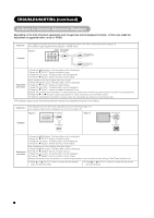
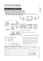
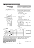
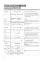
OPERATING INSTRUCTIONS (continued) Displaying MULTI PICTURE If the PinP button on the remote control is pressed MULTI PICTURE will display. Activating the P-in-P mode from the RGB input screen A/B button PinP button RECALL button RETURN button SELECT button Pressing the PinP button one time will display 2 pictures. • This mode can be available from RGB1(DVI-PC) and RGB2(RGB) input. • The speaker icon can be shifted up and down by pressing the A/B button; the audio of the video will be output from the side on which the speaker icon is located. • The sub-screen position can be selected up and down by pressing SELECT buttons. RGB2 AV1 • The sub-screen can be selected with the AV1, AV2, AV3, AV4 and TV channel number buttons from the status that the speaker icon appears on the left side of AV✱ as shown in (Subscreen) the diagram to the right. • Pressing the PinP button again or the RETURN button will cancel the 2 pictures display. • "Frequency Mode" in the Setup Menu should be set to Movie when sub-screen is the component signal of 1080i/50 or 1080i/60. AV1: Displays the VIDEO input signal of the sub-screen. Activating the Split mode from the video input screen 2 Pictures (Split) Pressing the PinP button one time will display 2 pictures. AV1 AV2 • The speaker icon can be shifted left and right by pressing the A/B button; the audio of the video will be output from the side on which the speaker icon is located. • The same video input mode cannot be selected for both screens at the same time. • Pressing the PinP button again or the RETURN button will cancel the 2 pictures display. • When the Video input is set to RGB Video, this Split mode is not possible. • Refer to the table for 2 pictures (Split) mode. Input terminal Main Sub AV1 AV4 PAL-N NTSC-M , PAL-M 576i, 576p 480i, 480p AV1 AV2 1080i/50 1080i/60 720p/60 RGB1 STB RGB2 Component AV1 AV4 PAL-N NTSC-M PAL-M AV1, AV2 RGB1 RGB2 576i 576p 480i 480p 1080i/50 1080i/60 720p/60 STB Component Main Sub ( NOTE • Even if the input of the horizontal / vertical synchronizing signal (or video signal) stops in the MULTI PICTURE display, the mode will not change to power save mode. • Please be careful since image retention will occur if display is left in a MULTI PICTURE display state for a long period of time. Input Signal Screen Display The input signal status can be displayed on the screen by pressing the RECALL button of the remote control or the monitor. • The display will go out in approximately 6 seconds. VIDEO Off-timer On-timer OFF -- -- Min. ON AV1 Composite Input mode Signal mode
-
 1
1 -
2
-
3
-
4
-
5
-
6
-
7
-
8
-
9
-
10
-
11
-
12
-
13
-
14
-
15
-
16
-
17
-
18
-
19
-
20
-
21
-
22
-
23
-
24
-
25
-
26
-
27
-
28
-
29
-
 30
30 -
 31
31 -
 32
32 -
 33
33 -
 34
34 -
 35
35 -
 36
36 -
 37
37 -
 38
38 -
 39
39 -
 40
40 -
41
-
42
-
43
-
44
-
45
-
46
-
47
-
48
-
49
-
50
-
51
-
52
-
53
-
54
-
55
-
56
-
57
-
58
-
59
-
60
-
61
-
62
-
63
-
64
-
65
-
66
 |
 |