Hitachi 42EDT41 Owners Guide - Page 58
PRODUCT SPECIFICATIONS continued, Signal Input - t com board
 |
View all Hitachi 42EDT41 manuals
Add to My Manuals
Save this manual to your list of manuals |
Page 58 highlights
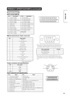
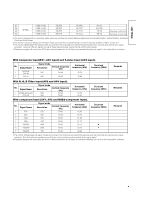
PRODUCT SPECIFICATIONS (continued) ENGLISH Signal Input DVI terminal (DVI-D) Pin Input signal Pin Input signal 1 T.M.D.S. Data2- 14 +5V Power 2 T.M.D.S. Data2+ 15 Ground (for+5V) 3 T.M.D.S. Data2/4 Shield 16 Hot Plug Detect 4 T.M.D.S. Data4- 17 T.M.D.S. Data0- 5 T.M.D.S. Data4+ 18 T.M.D.S. Data0+ 6 DDC Clock 19 T.M.D.S. Data0/5 Shield 7 DDC Data 20 T.M.D.S. Data5- 8 No Connect 21 T.M.D.S. Data5+ 9 T.M.D.S. Data1- 22 T.M.D.S. Clock Shield 10 T.M.D.S. Data1+ 23 T.M.D.S. Clock+ 11 T.M.D.S. Data1/3 Shield 24 T.M.D.S. Clock- 12 T.M.D.S. Data3- Frame GND 13 T.M.D.S. Data3+ 1 23 4 56 7 8 9 10 11 12 13 14 15 16 17 18 19 20 21 22 23 24 RGB terminal (D-sub 15-pin connector) Pin 1 2 3 4 5 6 7 8 9 10 11 12 13 14 15 Input signal R (PR/CR) G or sync on green (Y) B (PB/CB) No connection No connection R.GND (PR/CR, GND) G.GND (Y, GND) B.GND (PB/CB, GND) No connection GND No connection [SDA] H. sync or H/V composite sync V.sync. [V.CLK] [SCL] • When different kinds of input signals are simultaneously input to the monitor via a graphics board or the like, the monitor will automatically select the signals in the following priority order: Sync signal type H/V separate sync. H/V composite sync. sync.on Green * Priority 1 2 3 *Even in the case of the recommended signals shown on the following page, there may be instances when correct display is not possible. In this case, use H/V separate sync, H/V composite sync. ( ) : With component input S-input connector pin specifications Pin 1 2 3 4 Frame Input signal Y Y-GND C C-GND GND ᶅ ᶆ Scart connector pin specifications Pin Signal Pin Signal 1 AUDIO OUT (RIGHT) 2 AUDIO IN (RIGHT) 3 AUDIO OUT (LEFT/MONO) 4 AUDIO GND 5 RGB-B GND 6 AUDIO IN (LEFT/MONO) 7 RGB-B IN 8 AUDIO/RGB SWITCH / 16:9 9 RGB-G GND 10 Not Used 11 RGB-G IN 12 Not Used 13 RGB-R GND 14 GND 15 RGB-R / S.VHS CHROMINANCE IN 16 BLANKING SIGNAL 17 COMPOSITE VIDEO GND 18 BLANKING SIGNAL GND 19 COMPOSITE VIDEO OUT 20 COMPOSITE VIDEO / S.VHS LUMINANCE IN 21 GND / SHIELD (CHASSIS) ᶃ ᶄ 20 18 16 14 12 10 8 6 4 2 21 19 17 15 13 11 9 7 5 3 1
-
 1
1 -
2
-
3
-
4
-
5
-
6
-
7
-
8
-
9
-
10
-
11
-
12
-
13
-
14
-
15
-
16
-
17
-
18
-
19
-
20
-
21
-
22
-
23
-
24
-
25
-
26
-
27
-
28
-
29
-
30
-
31
-
32
-
33
-
34
-
35
-
36
-
37
-
38
-
39
-
40
-
41
-
42
-
43
-
44
-
45
-
46
-
47
-
48
-
49
-
50
-
51
-
52
-
 53
53 -
 54
54 -
 55
55 -
 56
56 -
 57
57 -
 58
58 -
 59
59 -
 60
60 -
 61
61 -
 62
62 -
 63
63 -
64
-
65
-
66
 |
 |
