Hitachi 65F710 Owners Guide - Page 71
Disassembly/assembly Instructions
 |
View all Hitachi 65F710 manuals
Add to My Manuals
Save this manual to your list of manuals |
Page 71 highlights
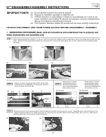
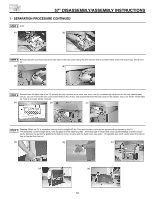
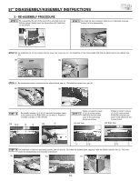
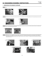
57" DISASSEMBLY/ASSEMBLY INSTRUCTIONS IMPORTANT POINTS: (a) Do not attempt to perform this work by yourself. (b) Request an installation specialist to install this unit. (c) HITACHI assumes no responsibility or liability for injury/damage as a result of con- sumer installation and handling. Be advised that improper consumer installation/handling is not covered by manufacturer's warranty. (d) This Projection Television weighs 205 pounds and has many sensitive components. CAUTION: DISCONNECT UNIT FROM POWER SOURCE BEFORE DISASSEMBLY / ASSEMBLY 1 - SEPARATION PROCEDURE (Note: read all instructions and understand how to properly and safely disassemble and assemble unit) STEP 1 Before disassembling this projection TV set, you must first remove the speaker grille by grabbing the sides and pulling left and right side see (a)(b). Remove the front decoration panels by unscrewing the 2 screws from each panel, see (c), then remove from the original position, see (d)(e). (a) (b) (c) (d) (e) STEP 2 Remove 4 screws that hold the screen frame to the cabinet on the Right side, see (a) and (b). Repeat to remove 4 screws on the Left side. (a) ብ ቤ ባ ቢ (b) ብ STEP 3 Please remove 3 screws below screen frame that hold the back cover to the cabinet as the arrows shows, see (a). Please remove 3 screws below screen frame that hold the back cover to the cabinet as the arrows shows, see (b). (a) Left Side (b) Right Side ቢ ባቤ ቤ ባ ቢ STEP 4 Remove the sensor box by unscrewing the 2 screws located on both sides of the sensor box, see (a). Rotate the sensor box and there are 4 low voltage connectors located on the sensor board, see (b). Disconnect the connector with the brown wires (PDSE), see (c) and (d). (Make sure to push the center lock on the connector at the unplug time.) (a) (b) 71
-
 1
1 -
2
-
3
-
4
-
5
-
6
-
7
-
8
-
9
-
10
-
11
-
12
-
13
-
14
-
15
-
16
-
17
-
18
-
19
-
20
-
21
-
22
-
23
-
24
-
25
-
26
-
27
-
28
-
29
-
30
-
31
-
32
-
33
-
34
-
35
-
36
-
37
-
38
-
39
-
40
-
41
-
42
-
43
-
44
-
45
-
46
-
47
-
48
-
49
-
50
-
51
-
52
-
53
-
54
-
55
-
56
-
57
-
58
-
59
-
60
-
61
-
62
-
63
-
64
-
65
-
 66
66 -
 67
67 -
 68
68 -
 69
69 -
 70
70 -
 71
71 -
 72
72 -
 73
73 -
 74
74 -
 75
75 -
 76
76 -
77
-
78
-
79
-
80
 |
 |