Hitachi 65F710 Owners Guide - Page 73
Re-assembly Procedure
 |
View all Hitachi 65F710 manuals
Add to My Manuals
Save this manual to your list of manuals |
Page 73 highlights
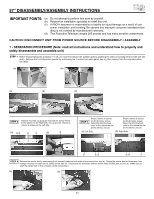
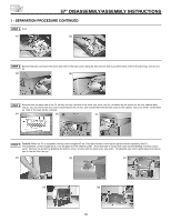
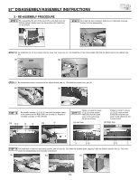
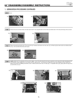
57" DISASSEMBLY/ASSEMBLY INSTRUCTIONS 2 - RE-ASSEMBLY PROCEDURE STEP 8 To re-assemble the set, lift the top portion and align onto the bottom cabinet. Gently lower the top portion until it sits flush on the bottom. STEP 9 Re-install the joint connector bolts (4 pcs.) that were removed in step 5 of the disassembly. STEP 10 Re-install the top (4) four screws into the lower rear cover, see (a). Re-install the (4) four side screws that hold the back cover to the cabinet, see (b). (a) (b) STEP 11 Re-connect the sensor connector to the sensor board, see (a). Re-install the sensor box, see (b). (a) (b) STEP 12 Re-install 4 screws that hold the screen frame to the cabinet on the Right side, see (a) and (b). Repeat to re-install 4 screws on the Left side. (a) ብ ቤ ባ ቢ (b) ብ STEP 13 Please re-install 3 screws below screen frame that hold the back cover to the cabinet as the arrows shows. (a) Left Side Please re-install 3 screws below screen frame that hold the back cover to the cabinet as the arrows shows. (b) Right Side ቢ ባቤ ቤ ባ ቢ STEP 14 Re-install both of the front decoration panels, see (a) and (b). Re-install the speaker grille, aligning it with the bottom cabinet, see (c). This com- pletes the Disassembly and Assembly instructions. (a) (b) (c) 73
-
 1
1 -
2
-
3
-
4
-
5
-
6
-
7
-
8
-
9
-
10
-
11
-
12
-
13
-
14
-
15
-
16
-
17
-
18
-
19
-
20
-
21
-
22
-
23
-
24
-
25
-
26
-
27
-
28
-
29
-
30
-
31
-
32
-
33
-
34
-
35
-
36
-
37
-
38
-
39
-
40
-
41
-
42
-
43
-
44
-
45
-
46
-
47
-
48
-
49
-
50
-
51
-
52
-
53
-
54
-
55
-
56
-
57
-
58
-
59
-
60
-
61
-
62
-
63
-
64
-
65
-
66
-
67
-
 68
68 -
 69
69 -
 70
70 -
 71
71 -
 72
72 -
 73
73 -
 74
74 -
 75
75 -
 76
76 -
 77
77 -
 78
78 -
79
-
80
 |
 |
