Hitachi CMP307XU Owners Guide - Page 10
Connecting to the PC, Installation and Cabling - specifications
 |
View all Hitachi CMP307XU manuals
Add to My Manuals
Save this manual to your list of manuals |
Page 10 highlights
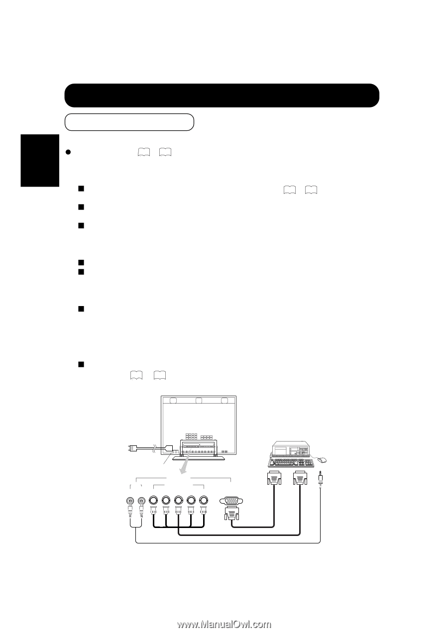
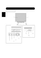
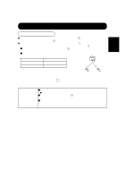
ENGLISH INSTALLATION INSTRUCTIONS (continued) Installation and Cabling Connecting to the PC Read Usage Notes ( 3 to 6 ) carefully to ensure maximum safety before proceeding to these steps: (1) Make sure that the display signals produced by your PC meet the specifications of this product. For the specifications of this product, see Product Specifications ( 28 to 30 ). (2) Choose an appropriate site and install the product on a level table where the stand is secure. Install the monitor to have ready access to a power socket. (3) Make sure that the monitor's power switch is off. The monitor is shipped with the power switch off. (4) Make sure that your PC's power switch is off. (5) Interconnect the signal input terminal (RGB1) on the monitor rear panel and the display signal output terminal of the PC to each other using the signal cable included. Optional cables are needed to connect to the RGB2 input and audio input terminals. If the signal cable included does not match your PC, consult your dealer after reading the section "Signal Input". (6) Insert one end of the power cable included into the rear-panel power cable connector and the other end into a power socket. If a power adapter is used, ground the grounding wire to avoid electrical shocks and radio interference. (Complete grounding before connecting the power plug to a power supply. Before disconnecting the grounding wire, be sure to disconnect the power plug from the power supply first.) (7) Turn on the monitor, then the PC to make sure that a display image appears on the monitor screen. For instructions on turning on the monitor and adjusting its display images, see "Operating Instructions" ( 13 to 21 ). Monitor rear panel Power cable Power cable connector RGB INPUT AUDIO RGB2 [ BNC ] (MONO) R L V H B G R RGB1 [ D-SUB ] PC To audio output terminal To signal output terminal To signal output terminal To signal input terminals To signal input terminals To audio input terminals 10
-
 1
1 -
2
-
3
-
4
-
 5
5 -
 6
6 -
 7
7 -
 8
8 -
 9
9 -
 10
10 -
 11
11 -
 12
12 -
 13
13 -
 14
14 -
 15
15 -
16
-
17
-
18
-
19
-
20
-
21
-
22
-
23
-
24
-
25
-
26
-
27
-
28
-
29
-
30
 |
 |