Hitachi DK23DA-30F Owners Manual - Page 90
condition. If no DEVICE CONFIGURATION SET command - 30f
 |
View all Hitachi DK23DA-30F manuals
Add to My Manuals
Save this manual to your list of manuals |
Page 90 highlights
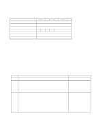
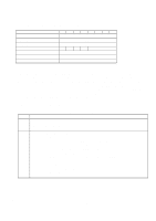
Word 3 - 6 7 8 - 254 255 Table 6.18 Device Configuration Identify Data Structure (continued) Description Value (HEX.) Maximum LBA Address Words 4 - 7 define the maximum LBA address. This is the highest address accepted by the device in the factory default condition. If no DEVICE CONFIGURATION SET command has been executed modifying the factory default condition, DK23DA-40F: 4A8 52FFh DK23DA-30F: 37E 3E3Fh DK23DA-20F: 254 297Fh DK23DA-10F: 12B B22Fh this is the same value as that returned by a READ NATIVE MAX ADDRESS command. Command Set / Feature Set Supported bit 15 - 9 0 = Reserved 008Fh bit 8 1= 48-bit Addressing feature set supported bit 7 1 = Host Protected Area feature set supported bit 6 1 = Automatic acoustic management supported bit 5 1 = R/W DMA QUEUED commands supported bit 4 1 = Power-up in Standby feature set supported bit 3 1 = Security feature set supported bit 2 1 = SMART error log supported bit 1 1 = SMART self-test supported bit 0 1 = SMART feature set supported Reserved 0000h Integrity word xxA5h bit 15 - 8 Checksum The checksum is the two's complement of the sum of all byte in words 0 through 254 and the byte consisting of bits 7:0 of word 255. Each byte is added with unsigned arithmetic, and overflow is ignored. The sum of all bytes is zero when the checksum is correct. bit 7 - 0 Signature Code "A5h" K6602705 Rev.3 08.20.01 - 90 -
-
 1
1 -
2
-
3
-
4
-
5
-
6
-
7
-
8
-
9
-
10
-
11
-
12
-
13
-
14
-
15
-
16
-
17
-
18
-
19
-
20
-
21
-
22
-
23
-
24
-
25
-
26
-
27
-
28
-
29
-
30
-
31
-
32
-
33
-
34
-
35
-
36
-
37
-
38
-
39
-
40
-
41
-
42
-
43
-
44
-
45
-
46
-
47
-
48
-
49
-
50
-
51
-
52
-
53
-
54
-
55
-
56
-
57
-
58
-
59
-
60
-
61
-
62
-
63
-
64
-
65
-
66
-
67
-
68
-
69
-
70
-
71
-
72
-
73
-
74
-
75
-
76
-
77
-
78
-
79
-
80
-
81
-
82
-
83
-
84
-
 85
85 -
 86
86 -
 87
87 -
 88
88 -
 89
89 -
 90
90 -
 91
91 -
 92
92 -
 93
93 -
 94
94 -
 95
95 -
96
-
97
-
98
-
99
-
100
-
101
-
102
-
103
-
104
-
105
-
106
-
107
-
108
-
109
-
110
-
111
-
112
 |
 |