Hitachi L42A403 Owners Guide - Page 15
Rear Panel Connections
 |
View all Hitachi L42A403 manuals
Add to My Manuals
Save this manual to your list of manuals |
Page 15 highlights
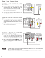
FIRST TIME USE Rear Panel Connections Outside antenna or Cable TV coaxial cable 2-Way signal splitter VCR ANT IN V LR RGB RGB HDMI to DVI DIGITAL OUTPUT AUDIO OUT HDMI DIGITAL OUTPUT CAPABILITY HDMI to HDMI HDMI OUTPUT DIGITAL OUTPUT CAPABILITY RGB OPTICAL IN OUTPUT Y PB/CB PR/CR L R OUTPUT S-Video Video L R NOTE STEREO SYSTEM AMPLIFIER Cables are not included. HDTV SET-TOP BOX DVD PLAYER with Component Output capability DVD PLAYER VIDEO GAME with Composite video capability Personal Computer TIPS ON REAR PANEL CONNECTIONS ♦♦ COMPONENT Y-PbPr (COMPONENT 1 & 2) or HDMI (1 & 2) connections are provided for high performance DVD players, VCRs etc. that have this feature. Use these connections in place of the standard video connection if your device has this feature. ♦♦ If your device has only one audio output (mono sound), connect it to the left audio jack on (L) the Rear Panel. ♦♦ Refer to the operating guide of your other electronic equipment for additional information on connecting your hook-up cables. ♦♦ Connect only 1 component (VCR, DVD player, camcorder, etc.) to each input jack. ♦♦ Your component outputs may be labeled Y, B-Y, and R-Y. In this case, connect the components B-Y output to the TV's Pb input and the components R-Y output to the TV's Pr input. ♦♦ Your component outputs may be labeled Y-CbCr. In this case, connect the components Cb output to the TV's Pb input and the components Cr output to the TV's Pr input. ♦♦ It may be necessary to adjust TINT to obtain optimum picture quality when using the Y-PbPr inputs. (See page 24). ♦♦ When using a HDMI input from a Set-Top-Box, it is recommended to use a 1080p, 1080i or 720p input signal. ♦♦ When the HDMI input is a 1080p signal, it is recommended that the length of the cable should be less than 5 meters. NOTES • Completely insert all connection cord plugs when connecting to rear panel jacks. The picture and sound that is played back will be abnormal if the connection is loose. • Cable plugs are often color-coded. Match colors of plugs and terminals, i.e. connect red to red, white to white, etc. Connecting a Personal Computer PC . Use the RGB PC connection terminal and the Analog Audio Input terminals to connect the PC. Manufactured under license from Dolby Laboratories. "Dolby" and the double-D symbol are trademarks of Dolby Laboratories. Fabriqué sous licence de Dolby Laboratories. Le terme « Dolby » 1. Connect the RGB (D-sub 15 Pin) and AUDIO et le sigle double D sont des marques commerciales de Dolby Laboratories. cable from the RGB and AUDIO OUT jack of the TruSurround HD, SRS and PC to the RGB symbol are trademarks of SRS and AUDIO jack, as shown on the Labs, Inc. Rear Panel on the right. IN (Audio) or OUT [PC sample] RGB RGB (D-sub 15 Pin) 2. Press the INPUT button, then select RGB from the INPUTS menu to view the signal from the PC. 15
-
 1
1 -
2
-
3
-
4
-
5
-
6
-
7
-
8
-
9
-
 10
10 -
 11
11 -
 12
12 -
 13
13 -
 14
14 -
 15
15 -
 16
16 -
 17
17 -
 18
18 -
 19
19 -
 20
20 -
21
-
22
-
23
-
24
-
25
-
26
-
27
-
28
-
29
-
30
-
31
-
32
-
33
-
34
-
35
-
36
-
37
-
38
-
39
-
40
-
41
-
42
-
43
-
44
-
45
-
46
-
47
-
48
-
49
-
50
-
51
 |
 |
