Hitachi M12V2 Instruction Manual - Page 13
Warning - router accessories
 |
UPC - 717709010376
View all Hitachi M12V2 manuals
Add to My Manuals
Save this manual to your list of manuals |
Page 13 highlights
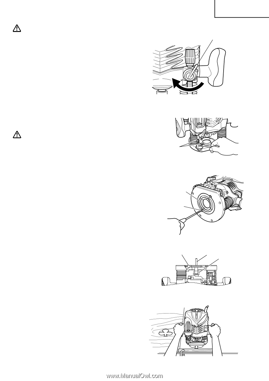
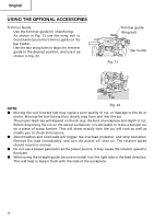
English CAUTION: Ensure that the lock lever is tightened after finely adjusting depth of cut. Failure to do so will result in damage to the quick adjustment lever. Quick adjustment lever 2. Stopper block (Fig. 8) The 2 cut-depth setting screws attached to the stopper block can be adjusted to simultaneously set 3 different cutting depth. Use a wrench to tighten the nuts so that the cut-depth setting screws do not come loose at this time. 3. Guiding the router Fig. 7 WARNING: Be sure to switch power OFF and disconnect the plug from the receptacle to avoid serious trouble. Cut depth setting screw (1) Template guide adapter Fig. 8 1 Loosen the 2 template guide adapter screws, so that the template guide adapter can be Template guide moved. (Fig. 9) adapter 2 Insert the centering gauge through the hole in the template guide adapter and into the Screw collet chuck. (Fig. 10) 3 Tighten the collet chuck by hand. 4 Tighten the template guide adapter screws, and pull out the centering gauge. (2) Template guide Fig. 9 Use the template guide when employing a template for producing a large quantity of identically shaped products. (Fig. 11) Template guide Centering gauge adapter Collet chuck As shown in Fig. 12, to install insert template guide in center hole in template guide adapter (A) with 2 accessory screws. If you are using a template guide adapter (B), it is possible to use template guides Fig. 10 produced by other firms. Attach template guides made by other firms to the template guide adapter (B). A template is a profiling mold made of plywood or thin lumber. When making a template, pay particular attention to the matters described below and illustrated in Fig. 13. Fig. 11 13
-
 1
1 -
2
-
3
-
4
-
5
-
6
-
7
-
 8
8 -
 9
9 -
 10
10 -
 11
11 -
 12
12 -
 13
13 -
 14
14 -
 15
15 -
 16
16 -
 17
17 -
 18
18 -
19
-
20
-
21
-
22
-
23
-
24
-
25
-
26
-
27
-
28
-
29
-
30
-
31
-
32
-
33
-
34
-
35
-
36
-
37
-
38
-
39
-
40
-
41
-
42
-
43
-
44
-
45
-
46
-
47
-
48
-
49
-
50
-
51
-
52
-
53
-
54
-
55
-
56
-
57
-
58
-
59
-
60
 |
 |