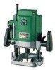
Hitachi M12V2 Instruction Manual - Page 15
Removing the spring, Cutting - router parts
 |
UPC - 717709010376
View all Hitachi M12V2 manuals
Add to My Manuals
Save this manual to your list of manuals |
Page 15 highlights
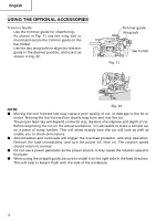
English 5. Removing the spring The springs within the column of the router can be removed. Doing so will eliminate spring resistance and allows easy adjustment of cutting depth when attaching the router stand. (1) Loosen the 4 sub base screws, and remove the sub base. (2) Loosen the stopper bolt and remove it, so the spring can be removed. (Fig. 18) Dust guide Screw Dust guide adapter Tab Tab Fig. 16 WARNING: Remove the stopper bolt with the main unit (router) fixed at its maximum height. Removing the stopper bolt with the unit in a shortened condition may cause the stopper bolt and spring to be discharged and cause injury. 6. Cutting WARNING: ⅷ Wear eye protection when operating this tool. ⅷ Keep your hands, face and other body parts away from the bits and any other rotating parts, while operating the tool. Stopper bolt Fig. 17 Fig. 18 Dial Spring (1) As shown in Fig. 19, remove the bit from the work pieces and press the switch lever up to the ON position. Do not start cutting operation until the bit has reached full rotating speed. (2) The bit rotates clockwise (arrow direction indicated on the base). To obtain maximum cutting effectiveness, feed the router in conformance with the feed directions shown in Fig. 20. NOTE: If a worn bit is used to make deep grooves, a high pitched cutting noise may be produced. Replacing the worn bit with a new one will eliminate the high pitched noise. Separate Fig. 19 Router feed Router feed Workpiece Rotation of bit Fig. 20 15
-
 1
1 -
2
-
3
-
4
-
5
-
6
-
7
-
8
-
9
-
 10
10 -
 11
11 -
 12
12 -
 13
13 -
 14
14 -
 15
15 -
 16
16 -
 17
17 -
 18
18 -
 19
19 -
 20
20 -
21
-
22
-
23
-
24
-
25
-
26
-
27
-
28
-
29
-
30
-
31
-
32
-
33
-
34
-
35
-
36
-
37
-
38
-
39
-
40
-
41
-
42
-
43
-
44
-
45
-
46
-
47
-
48
-
49
-
50
-
51
-
52
-
53
-
54
-
55
-
56
-
57
-
58
-
59
-
60
 |
 |
