Hitachi NR90AF Instruction Manual - Page 11
English
 |
UPC - 717709012875
View all Hitachi NR90AF manuals
Add to My Manuals
Save this manual to your list of manuals |
Page 11 highlights
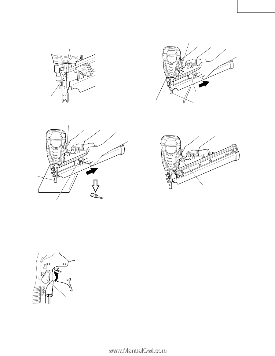
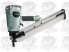
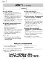
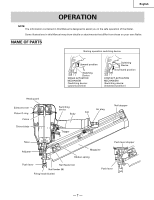
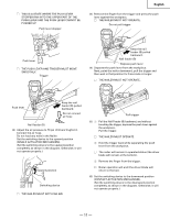
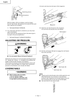
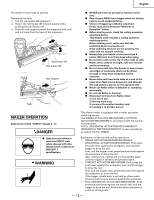
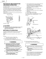
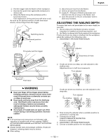
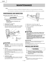
Ⅺ THIS IS A STATE WHERE THE PUSH LEVER STOPPER RAN INTO THE UPPER PART OF THE PUSH LEVER AND THE PUSH LEVER CANNOT BE PUSHED UP. Push lever stopper English (3) Remove the finger from the trigger and press the push lever against the workpiece. Ⅺ THE NAILER MUST NOT OPERATE. Do not pull trigger Push lever Ⅺ THE PUSH LEVER AND TRIGGER MUST MOVE SMOOTHLY. Trigger Keep the nail feeder (B) pulled backward. Nail feeder (B) Depress push lever (4) Separate the push lever from the workpiece. Next, point the nailer downward, pull the trigger and then wait in that position for 5 seconds or longer. Ⅺ THE NAILER MUST NOT OPERATE. Push lever Keep the nail feeder (B) pulled backward. Do not connect air hose Nail feeder (B) (2) Adjust the air pressure to 70 psi (4.9 bars 5 kgf/cm2). Connect the air hose. Do not load any nails in the Nailer. Set the switching device to the upward position (SINGLE ACTUATION MECHANISM). (Set the switching device to the upward position completely as shown in the diagram. Otherwise, it will not operate properly.) Upward position Switching device Ⅺ THE NAILER MUST NOT LEAK AIR. Pull trigger (5) 1 Pull the Nail Feeder (B) backward, and without touching the trigger, depress the push lever against the workpiece. Pull the trigger. Ⅺ THE NAILER MUST OPERATE. 2 Hold the trigger back while separating the push lever from the workpiece. Ⅺ The nailer will remain in operated status (the driver blade will remain at the bottom). 3 Remove the finger from the trigger. Ⅺ Nailer operation will end (the driver blade will return to the top). (6) Set the switching device to the downward position (CONTACT ACTUATION MECHANISM). (Set the switching device to the downward position completely as shown in the diagram. Otherwise, it will not operate properly.) - 11 -
-
 1
1 -
2
-
3
-
4
-
5
-
 6
6 -
 7
7 -
 8
8 -
 9
9 -
 10
10 -
 11
11 -
 12
12 -
 13
13 -
 14
14 -
 15
15 -
 16
16 -
17
-
18
-
19
-
20
-
21
-
22
-
23
-
24
-
25
-
26
-
27
-
28
-
29
-
30
-
31
-
32
-
33
-
34
-
35
-
36
-
37
-
38
-
39
-
40
-
41
-
42
-
43
-
44
-
45
-
46
-
47
-
48
-
49
-
50
-
51
-
52
-
53
-
54
-
55
-
56
 |
 |