Honeywell 4800dr Barcode Guide - Page 13
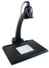
TTL-232 Serial Port Connection, Aligning the Document Reader Tray, ACK/NAK Mode - document image
 |
View all Honeywell 4800dr manuals
Add to My Manuals
Save this manual to your list of manuals |
Page 13 highlights
ACK/NAK Mode On * Off TTL-232 Serial Port Connection All communication parameters between the document reader and terminal must match for correct data transfer through the serial port using RS-232 protocol. Scanning the RS-232 interface barcode programs the document reader for an RS-232 interface at 115,200 baud, parity-none, 8 data bits, 1 stop bit, and adds a suffix of a CR LF. TTL-232 Interface Aligning the Document Reader Tray Proper cable placement is important for accurate alignment of the device. Place the cable in the wire channel if the imager will remain in the base most of the time. If you plan to frequently lift out the imager to scan items, then set the cable in the location where it will rest while the imager is in the stand. Note: The 4800dr will not capture any images until it has been properly aligned using the following procedure. 1. Loosen the screw in the base tray with a coin. 2. Place the alignment page on the tray. Align the upper left corner of the alignment page to the upper left corner of the tray. 3. Make sure the serial number on the alignment page (the top number) matches the serial number on your document reader. 4800dr s/n engine s/n 4. Press the button on the imager to display the illuminated aimer crosshairs. You will hear a single beep that indicates you are using the correct page. (If you hear 3 beeps and the aimer turns off, then you have the wrong alignment page for your document reader.) 5. Move the tray until the illuminated aimer crosshairs line up with the printed crosshairs on the alignment page. (Be sure to wait until the crosshairs go off before removing power or attempting to capture an image.) 6. Remove the alignment page and tighten the screw. Save the alignment page in the event that the tray needs to be realigned in the future. Note: If you need to print a new copy of the alignment page, make sure to print the page in landscape mode. 1 - 5
-
 1
1 -
2
-
3
-
4
-
5
-
6
-
7
-
 8
8 -
 9
9 -
 10
10 -
 11
11 -
 12
12 -
 13
13 -
 14
14 -
 15
15 -
 16
16 -
 17
17 -
 18
18 -
19
-
20
-
21
-
22
-
23
-
24
-
25
-
26
-
27
-
28
-
29
-
30
-
31
-
32
-
33
-
34
-
35
-
36
-
37
-
38
-
39
-
40
-
41
-
42
-
43
-
44
-
45
-
46
-
47
-
48
-
49
-
50
-
51
-
52
-
53
-
54
-
55
-
56
-
57
-
58
-
59
-
60
-
61
-
62
-
63
-
64
-
65
-
66
-
67
-
68
-
69
-
70
-
71
-
72
-
73
-
74
-
75
-
76
-
77
-
78
-
79
-
80
-
81
-
82
-
83
-
84
-
85
-
86
-
87
-
88
-
89
-
90
-
91
-
92
-
93
-
94
-
95
-
96
-
97
-
98
-
99
-
100
-
101
-
102
-
103
-
104
-
105
-
106
-
107
-
108
-
109
-
110
-
111
-
112
-
113
-
114
-
115
-
116
-
117
-
118
-
119
-
120
-
121
-
122
-
123
-
124
-
125
-
126
-
127
-
128
-
129
-
130
-
131
-
132
-
133
-
134
-
135
-
136
-
137
-
138
-
139
-
140
-
141
-
142
-
143
-
144
-
145
-
146
 |
 |
