Honeywell 5800PIR-RES Installation Instructions - Page 5
Perform a Walk Test, Program the Control Panel - instructions
 |
View all Honeywell 5800PIR-RES manuals
Add to My Manuals
Save this manual to your list of manuals |
Page 5 highlights
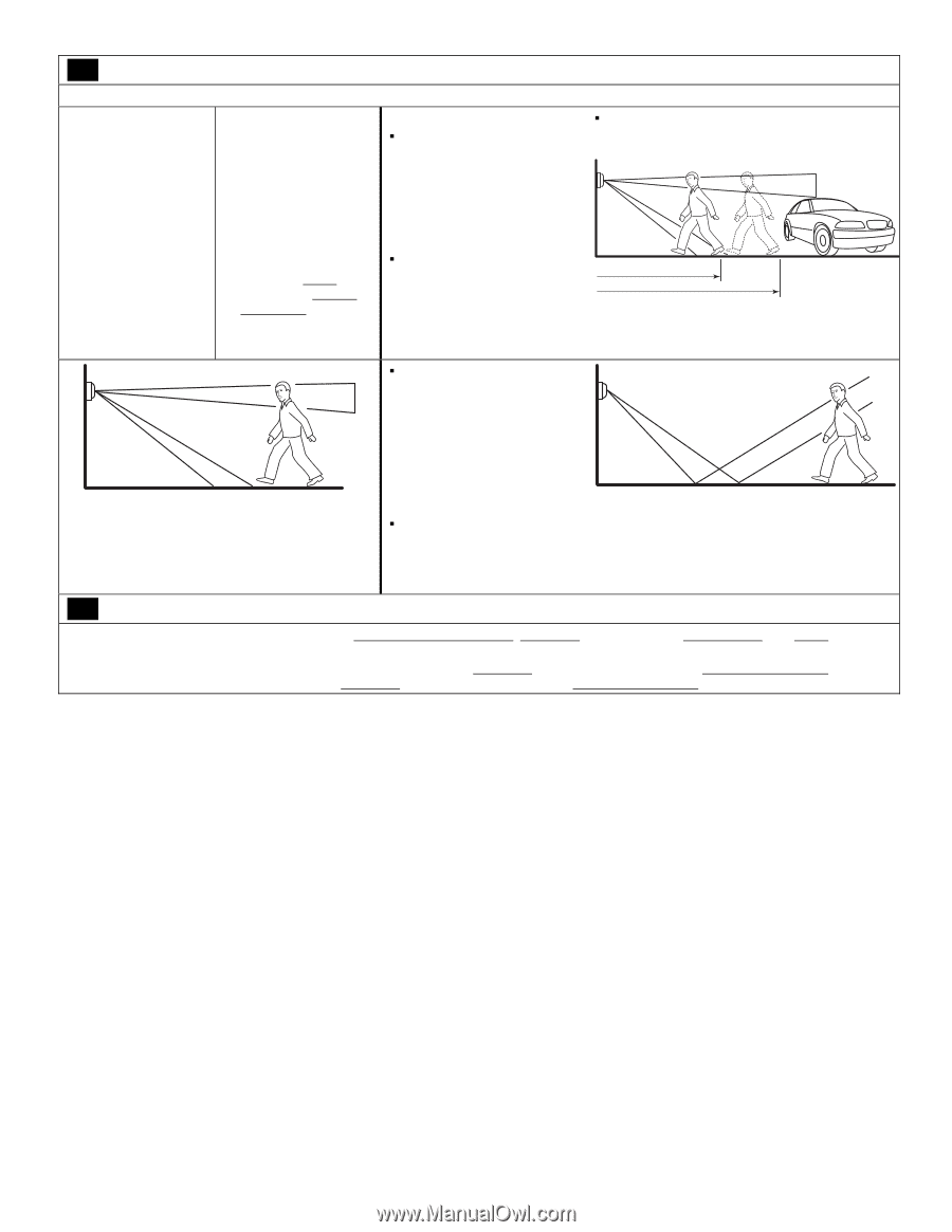
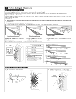
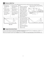
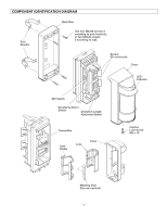
6 Perform a Walk Test NOTE: With the Walk Test switch set to ON the LED will light when the detector is tripped, and the alarm is generated instantly. 1. Set the walk test switch (DIP switch 1) to ON. Replace the cover. 2. Perform a walk test through the detection area, and verify satisfactory results. 3. Allow the detection area to remain static, and check for false or unwanted detections. 4. If necessary, adjust the detection area (see Perform Settings & Adjustments). 5. Repeat the walk test through the detection area, and verify satisfactory results. 6. Set the walk test DIP switch 1 to OFF, and secure the Cover with the M3 x 10 Captive Lock Screw. Notes: ƒ If normal car or people traffic pass close to the detection area, adjust the detection area 1.5 to 2.0m (5 to 7ft) shorter to reduce false detections. This also allows for changes due to environmental thermal conditions. ƒ If the detection length is adjusted to position "A" [12m (40ft)], the detection area may increase when there is a big temperature difference between the moving object and the background. ƒ If this causes a problem, adjust the detection length to position "B". Then walk test to verify satisfactory results. Approx.8m (27ft) position B Approx.12m (40ft) WALK TEST ƒ This sensor has a multi-level detection pattern (from side view). A heat source beyond the detection area may cause the detector to issue a false alarm by reflecting off the ground. Examples include puddles, wet surfaces, very smooth asphalt or concrete surfaces. ƒ If this causes a problem, adjust the detection length to position "B". Then perform a walk test to verify satisfactory results. 7 Program the Control Panel Prior to use in the system, you must program the transmitter's serial number, input type (RF Supervised), response type, and loop # (set to 1) in the control panel. Refer to the control panel's instructions for further details. Note: If you are learning the control panel by walking, either use the Walk Test setting or temporally set the Battery Saving Timer to 5 sec. When the programming is complete ensure the Walk Test switch is set to OFF, and the Battery Saving Timer is set to your desired setting. - 5 -
-
 1
1 -
 2
2 -
 3
3 -
 4
4 -
 5
5 -
 6
6 -
 7
7 -
 8
8
 |
 |