Honeywell 5800PIR-RES Installation Instructions - Page 7
Component Identification Diagram
 |
View all Honeywell 5800PIR-RES manuals
Add to My Manuals
Save this manual to your list of manuals |
Page 7 highlights
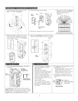
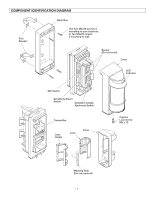
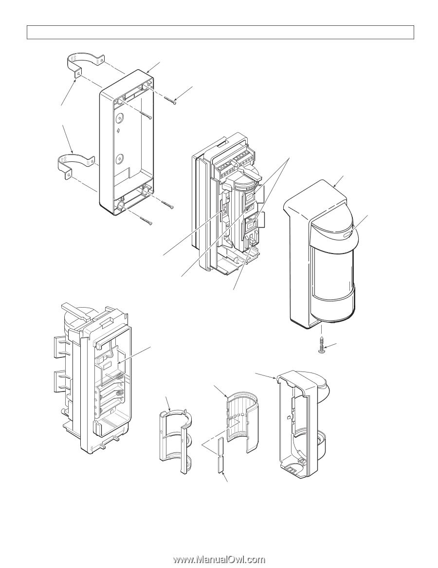
COMPONENT IDENTIFICATION DIAGRAM Pole Bracket Back Box Use four M4x30 screws if mounting to pole brackets, or two M4x20 screws if mounting to wall. UP Sensor (Do not touch) Cover LED Indicator DIP Switch Sensitivity Select Switch Detection Length Ajustment Switch Transmitter Lens Holder Lens Cover Captive Lock Screw M3 x 10 Masking Strip (Use as required) - 7 -
-
 1
1 -
 2
2 -
 3
3 -
 4
4 -
 5
5 -
 6
6 -
 7
7 -
 8
8
 |
 |
– 7 –
COMPONENT IDENTIFICATION DIAGRAM
Transmitter
Sensor
(Do not touch)
Cover
LED
Indicator
Cover
Lens
Back Box
Use four M4x30 screws if
mounting to pole brackets,
or two M4x20 screws
if mounting to wall.
Captive
Lock Screw
M3 x 10
Masking Strip
(Use as required)
Lens
Holder
UP
DIP Switch
Sensitivity Select
Switch
Detection Length
Ajustment Switch
Pole
Bracket