Honeywell PRO22IC Installation Manual - Page 9
Description, Set Up - boards
 |
View all Honeywell PRO22IC manuals
Add to My Manuals
Save this manual to your list of manuals |
Page 9 highlights
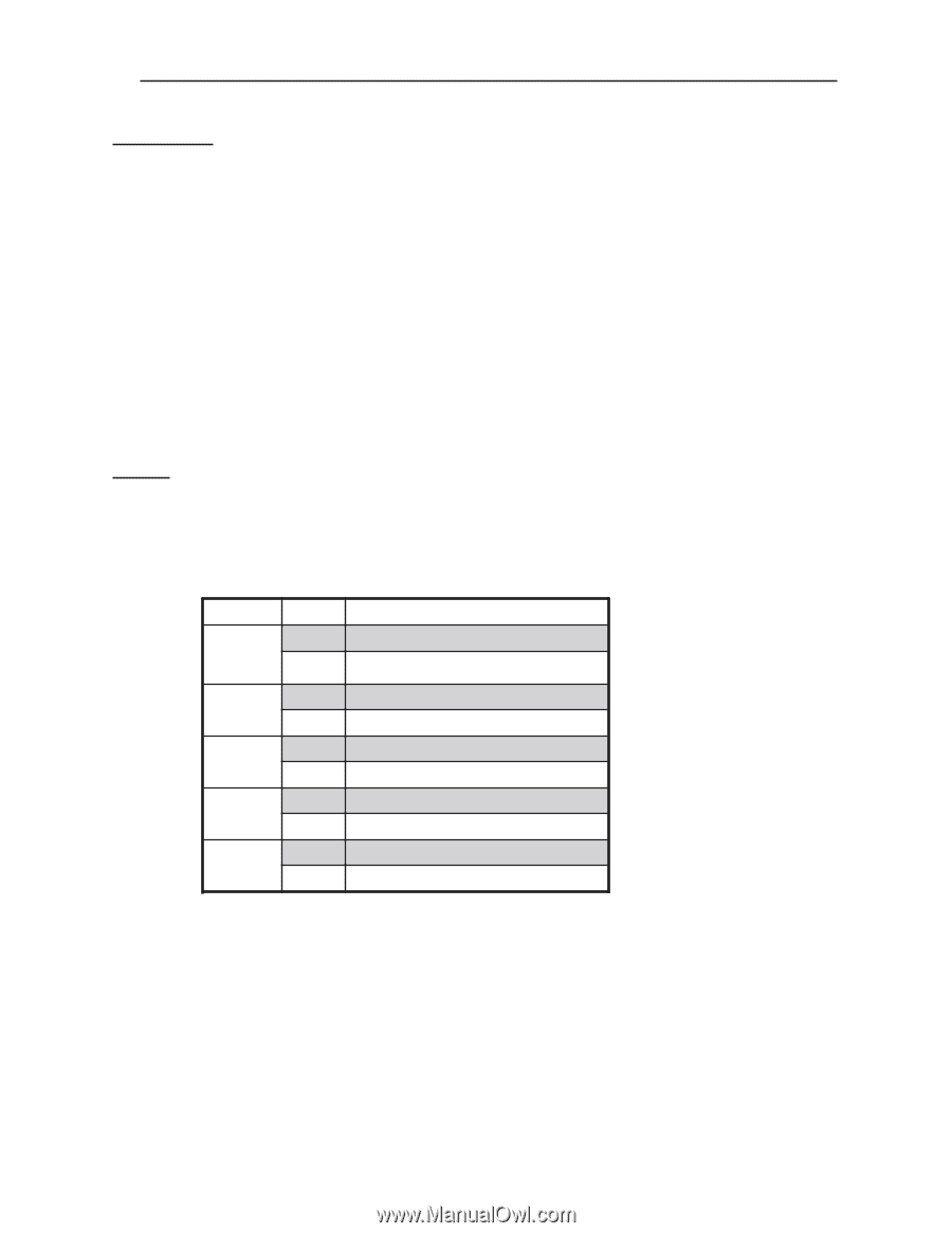
PRO-2200 Intelligent Controller PRO22IC Installation Guide 9 Description The Intelligent Controller is the heart of the PRO-2200 and provides the real time processing for the connected I/O interfaces. It holds the database for the subsystem configuration and card holders, and the event log buffer in battery-backed memory. Port 1 provides the standard connection to the host computer. 1. Port 1 may be set up as an RS-232 interface or an RS-485 interface. An optional interface board (PRO22EN) converts the RS-232 output of port 1 into an Ethernet port capable of supporting TCP/IP. If this interface board is present, this port must be set up as an RS-232 interface and Jumper J-14 must be removed. 2. Ports 2 & 3 are RS-485 interfaces. An on-board real time clock maintains the date and time, taking into account leap year and accounting for global time zones and daylight savings time changes. The program is stored in FLASH memory and may be downloaded through a serial port, allowing the program to be changed without physically changing board components. Set Up The controller hardware is configured with jumpers and a set of eight switches. These jumpers/switches setup the memory chip size, port interface, end of line termination, controller address, and baud rate. Please refer to the tables. Jumper Settings: JUMPERS J4,5,6 J14 J9 J12 J13 SET AT 2-3 1-2 OFF ON OFF ON OFF ON OFF ON SELECTED PORT 1 IS RS-232 PORT 1 IS RS-485 PORT 1 IS ETHERNET, COBOX MICRO PORT 1 IS RS-232 OR RS-485 PORT 1 RS-485 EOL TERMINATOR IS NOT ON PORT 1 RS-485 EOL TERMINATOR IS ON PORT 2 RS-485 EOL TERMINATOR IS NOT ON PORT 2 RS-485 EOL TERMINATOR IS ON PORT 3 RS-485 EOL TERMINATOR IS NOT ON PORT 3 RS-485 EOL TERMINATOR IS ON
-
 1
1 -
2
-
3
-
 4
4 -
 5
5 -
 6
6 -
 7
7 -
 8
8 -
 9
9 -
 10
10 -
 11
11 -
 12
12 -
 13
13 -
 14
14 -
15
-
16
 |
 |