Honeywell Q682B Owner's Manual - Page 24
Thermometer Adjustment
 |
View all Honeywell Q682B manuals
Add to My Manuals
Save this manual to your list of manuals |
Page 24 highlights
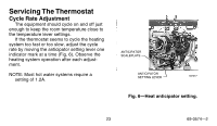
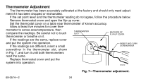
Thermometer Adjustment The thermometer has been accurately calibrated at the factory and should only need adjust- ment if it has been dropped or mishandled. If the set point lever and the thermometer reading do not agree, follow the procedure below. Remove thermostat cover and open the flip-up cover. Set the thermostat cover on a table near thermometer of known accuracy. Allow at least five minutes for cover ther- mometer to sense area temperature, then compare the readings. Be careful not to touch thermometer or breathe on it. THERMOMETER SLOT BACKSIDE OF FLIP-UP COVER If the readings are the same, replace cover and put the system into operation. If the readings are different, insert a small INSERT AND TURN SCREWDRIVER screwdriver in the thermometer slot, shown in Fig. 7, and turn it until both thermometers read the same. Replace thermostat cover and put the system into operation. M1810 Fig. 7-Thermometer adjustment. 69-0574-2 24
-
 1
1 -
2
-
3
-
4
-
5
-
6
-
7
-
8
-
9
-
10
-
11
-
12
-
13
-
14
-
15
-
16
-
17
-
18
-
 19
19 -
 20
20 -
 21
21 -
 22
22 -
 23
23 -
 24
24 -
 25
25 -
 26
26 -
 27
27 -
 28
28
 |
 |
