Honeywell T812C1000 Installation Instructions - Page 2
Wiring and Mounting - international
 |
View all Honeywell T812C1000 manuals
Add to My Manuals
Save this manual to your list of manuals |
Page 2 highlights
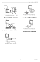
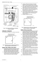
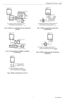
T812, TS812 THERMOSTATS MOUNTING HOLE (THERMOSTAT TO WALL) MOUNTING TABS (3) SNAP SWITCH CONTACTS TEMPERATURE SETTING LEVER 3. Connect the thermostat wires to the appropriate terminals on the thermostat back. See Fig. 4-8 for typical hookup diagrams. 4. Push any excess wire back through the hole and plug any opening to prevent drafts that could affect thermostat performance. 5. Adjust the heat anticipator (select models) to match the current draw of the system primary control. See Heat Anticipator Setting section. 6. Fasten the thermostat to the wall with screws through the mounting holes on the upper left and right sides of the device. See Fig. 2. 7. Replace the thermostat cover. MOUNTING HOLES (2) USED TO MOUNT THERMOSTAT TO WALL (FOR MODELS WITH SUBBASE). SCREWS (3) USED TO MOUNT THERMOSTAT ONTO SUBBASE BIMETAL ELEMENT ADJUSTABLE HEAT ANTICIPATOR INDICATOR LEVER ADJUSTABLE HEAT ANTICIPATOR SCALE MOUNTING HOLE (THERMOSTAT TO WALL) M20496A Fig. 1. Internal view of T812 with adjustable heat anticipator. Wiring and Mounting All wiring must comply with local codes and ordinances. MOUNTING HOLES (2) USED TO MOUNT THERMOSTAT TO WALL (FOR MODELS WITHOUT SUBBASE). M20883 Fig. 2. Mounting hole locations for models without subbase. T812 and TS812 Models Without Subbase 1. In replacement applications, inspect the old wires for frayed or cracked insulation and replace any wires in poor condition; in new installations, run two wires to the location. 2. Grasping the thermostat cover on the top and the bottom with one hand, push in on the bottom center and pull outward until the cover snaps free from the thermostat base. M20889 Fig. 3. Mounting hole locations for models with subbase. T812 Models With Subbase 1. In replacement applications, inspect the old wires for frayed or cracked insulation and replace any wires in poor condition; in new installations, run the appropriate number of wires to the location. 2. Grasping thermostat cover on top and bottom with one hand, push in on bottom center and pull outward until cover snaps free from thermostat base. 3. Disconnect thermostat from subbase by unscrewing the three screws under the thermostat cover. See Fig. 1. 4. Connect the wires to the terminals on the front of the subbase. See Fig. 4-8. 5. Push any excess wire back through the hole and plug any opening to prevent drafts that could affect thermostat performance. 6. Loosely fasten thermostat subbase to the wall with a screw through the right mounting hole. Adjust the subbase so it is approximately level and start the second screw through the left mounting slot. 7. Level the thermostat subbase for appearance only; it is not required for accurate operation. 8. Tighten the mounting screws. See Fig. 3. 9. Mount the thermostat to the thermostat subbase by tightening the three screws. See Fig. 1. 10. Adjust the heat anticipator (select models) to match the current draw of the system primary control. See Heat Anticipator Setting section. 11. Replace the thermostat cover. 69-1606ESF-3 2
-
 1
1 -
 2
2 -
 3
3 -
 4
4 -
 5
5 -
 6
6 -
 7
7 -
 8
8 -
9
-
10
-
11
-
12
 |
 |
