Honeywell TH5110D1006 Installation Guide - Page 4
Wiring - thermostat
 |
UPC - 085267256988
View all Honeywell TH5110D1006 manuals
Add to My Manuals
Save this manual to your list of manuals |
Page 4 highlights
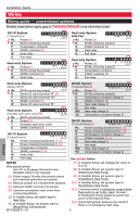
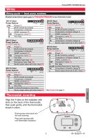
Installation Guide Wiring Wiring guide - conventional systems Shaded areas below apply only to TH5320U/TH5220D or as otherwise noted. 1H/1C System (1 transformer) Rc Power [1] G W C Y R Rc M29372 R [R+Rc joined by jumper] Y Compressor contactor C 24VAC common [3] W Heat relay G Fan relay Heat-only System Rc Power [1] W C R Rc M29373 R [R+Rc joined by jumper] C 24VAC common [3] W Heat relay Heat-only System with Fan GWC Rc Power [1] R [R+Rc joined by jumper] C 24VAC common [3] W Heat relay G Fan relay R Rc M29377 Cool-only System Rc Power [1] G R [R+Rc joined by jumper] Y Compressor contactor C 24VAC common [3] G Fan relay C Y R Rc M29378 ENGLISH Heat-only System (Series 20) [5] Rc [R+Rc joined by jumper] W C Y R Rc M29374 2H/2C System (1 transformer) [6] Rc Power [1] Y2 W2 G W C Y R Rc M29379 R Series 20 valve terminal "R" [1] R [R+Rc joined by jumper] Y Series 20 valve terminal "W" Y Compressor contactor (stage 1) C 24VAC common [3] C 24VAC common [3] W Series 20 valve terminal "B" W Heat relay (stage 1) Heat-only System (normally open zone valve) [5] Rc [R+Rc joined by jumper] C Y R Rc M29375 G Fan relay W2 Heat relay (stage 2) Y2 Compressor contactor (stage 2) R Power [1] Y Normally open zone valve C 24VAC common [3] 2H/2C System (2 transformers) [6] Y2 W2 G W C Y R Rc Rc Power (cooling transformer) [1, 2]M29380 1H/1C System (2 transformers) G W C Y R Rc M29376 Rc Power (cooling transformer) [1, 2] R Power (heating transformer) [1, 2] Y Compressor contactor C 24VAC common [3, 4] W Heat relay R Power (heating transformer) [1, 2] Y Compressor contactor (stage 1) C 24VAC common [3, 4] W Heat relay (stage 1) G Fan relay W2 Heat relay (stage 2) Y2 Compressor contactor (stage 2) G Fan relay See [notes] below NOTES Wire specifications: Use 18- to 22-gauge thermostat wire. Shielded cable is not required. [7] In Installer Setup, set changeover valve to O or B. [8] In Installer Setup, set system type to 2Heat/1Cool Heat Pump. [1] Power supply. Provide disconnect means and overload protection as required. [2] Remove jumper for 2-transformer systems. [3] Optional 24VAC common connection. [4] Common connection must come from cooling transformer. [5] In Installer Setup, set system type to Heat Only. [6] In Installer Setup, set system type to 2Heat/2Cool Conventional. 69-1922EFS-01 [9] In Installer Setup, set system type to 2Heat/2Cool Heat Pump. [10] In Installer Setup, set system type to 3Heat/2Cool Heat Pump. [11] L terminal sends a continuous output when thermostat is set to Em. Heat. Connect to Honeywell zoning panels to switch the panel to Emergency Heat. [12] Install field jumper between Aux and E if there is no emergency heat relay. 4
-
 1
1 -
 2
2 -
 3
3 -
 4
4 -
 5
5 -
 6
6 -
 7
7 -
 8
8 -
 9
9 -
 10
10 -
11
-
12
-
13
-
14
-
15
-
16
-
17
-
18
-
19
-
20
-
21
-
22
-
23
-
24
 |
 |
