Honeywell TH5110D1006 Installation Guide - Page 5
Wiring, Thermostat mounting
 |
UPC - 085267256988
View all Honeywell TH5110D1006 manuals
Add to My Manuals
Save this manual to your list of manuals |
Page 5 highlights
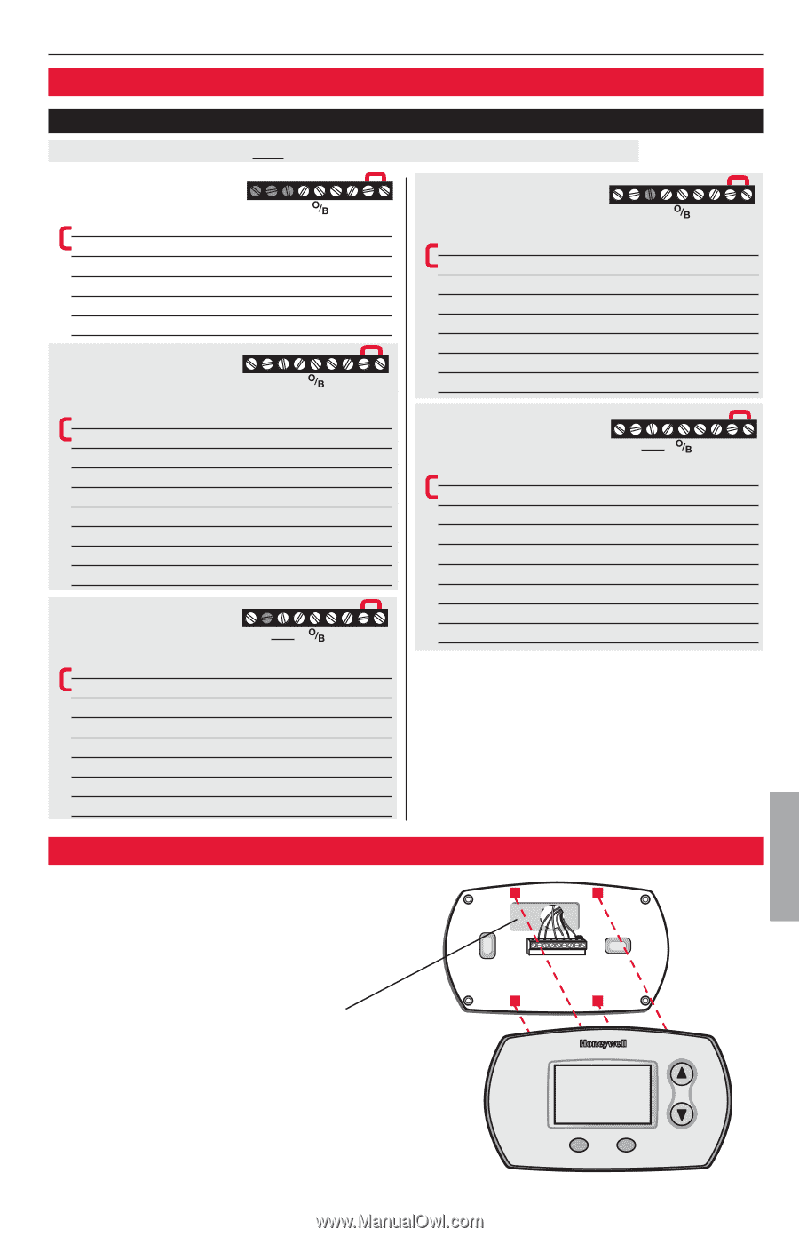
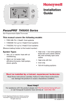
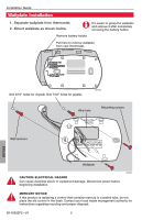
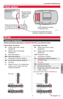
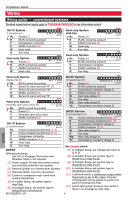
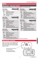
FocusPRO® TH5000 Series Wiring Wiring guide - heat pump systems Shaded areas below apply only to TH5320U/TH5220D or as otherwise noted. 1H/1C Heat Pump System G Rc Power [1] R [R+Rc joined by jumper] Y Compressor contactor C 24VAC common [3] O/B Changeover valve [7] G Fan relay C Y R Rc M29381 2H/1C Heat Pump System (TH5220D only) [8] L E Aux G C Y R Rc M29382 Rc Power [1] R [R+Rc joined by jumper] Y Compressor contactor C 24VAC common [3] O/B Changeover valve [7] G Fan relay Aux Auxiliary heat relay [12] E Emergency heat relay [12] L Sends output when set to Em. Heat [11] 2H/1C Heat Pump System (TH5320U only) [8] L Aux G E C Y R Rc M29383 Rc Power [1] R [R+Rc joined by jumper] Y Compressor contactor C 24VAC common [3] O/B Changeover valve [7] G Fan relay Aux/E Auxiliary/Emergency heat relay L Sends output when set to Em. Heat [11] 2H/2C Heat Pump System (TH5320U only) [9] L Y2 G C Y R Rc M29384 Rc Power [1] R [R+Rc joined by jumper] Y Compressor contactor (stage 1) C 24VAC common [3] O/B Changeover valve [7] G Fan relay Y2 Compressor contactor (stage 2) L Sends output when set to Em. Heat [11] 3H/2C Heat Pump System (TH5320U only) [10] L Y2AuxG C Y R Rc E M29385 Rc Power [1] R [R+Rc joined by jumper] Y Compressor contactor (stage 1) C 24VAC common [3] O/B Changeover valve [7] G Fan relay Aux/E Auxiliary/Emergency heat relay Y2 Compressor contactor (stage 2) L Sends output when set to Em. Heat [11] See [notes] on page 4. Thermostat mounting Align the 4 tabs on the wallplate with slots on the back of the thermostat, then push gently until the thermostat snaps in place. Push excess wire back into the wall opening. Plug wall opening with non-flammable insulation. ENGLISH M29386 5 69-1922EFS-01
-
 1
1 -
 2
2 -
 3
3 -
 4
4 -
 5
5 -
 6
6 -
 7
7 -
 8
8 -
 9
9 -
 10
10 -
 11
11 -
12
-
13
-
14
-
15
-
16
-
17
-
18
-
19
-
20
-
21
-
22
-
23
-
24
 |
 |