Hotpoint NVLR223GGWW Installation Instructions - Page 7
Installation, Instructions
 |
View all Hotpoint NVLR223GGWW manuals
Add to My Manuals
Save this manual to your list of manuals |
Page 7 highlights
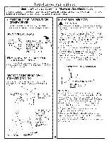
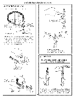
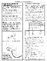
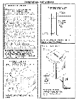
Installation I_ DRYER EXHAUST TO LEFT OR BOTTOM CABINET WARNING- BEFORE PERFORMING THIS EXHAUST INSTALLATION, BE SURE TO DISCONNECT THE DRYER FROM ITS ELECTRICAL SUPPLY. PROTECT YOUR HANDS AND ARMS FROM SHARP EDGES WHEN WORKING INSIDE THE CABINET. BE SURE TO WEAR GLOVES Instructions ADDING NEW DUCT FIXING HOLE PORTIO"NA" REMOVE SCREW ANDSAVE. O_ REMOVE DESIRED KNOCKOUT (ONEONLY). Detach and remove the bottom or left side knockout as desired. Remove the screw inside the dwer exhaust duct and save. Pull the duct out of the duet. FIXINGHOLE B A 9" Cut the duct as shown and kee I) portion A. TAB LOCATION LEFTSIDE EXHAUST Reconnect dm cut portion (A) of the duct to the blower housing. Make sure that the shortened duct is aligned with the tab in the base. Use the screw saved previously to secure the duct in place through the tab on the appliance base. ADDING ELBOW AND DUCT FOR EXHAUST TO LEFT SIDE OF CABINET • Preassemble 4" elbow with 4" duct. Wrap duct tape around joint. • Insert duct assembly, elbow first, through the side opening and connect the elbow to the dwer internal duct. CAUTION: Be sure not to pull or damage the electrical wires inside the dryer when inserting the duct, J_ DUCT // TAPE BENDTAB UP450 Through the real" opening, locate the tab in the middle of the appliance base. Lift the tab to about 45 ° using a fiat blade screwdriver. • Apply duct tape as shown on the joint between the diTer internal duct and the elbow. DUCT TAPE CAUTION: Internal duct joints must be __ stheecyurmedaywisthepataraptee, oanthdercwaiussee 7 a safety hazard.
-
 1
1 -
 2
2 -
 3
3 -
 4
4 -
 5
5 -
 6
6 -
 7
7 -
 8
8
 |
 |
