Hotpoint NWXR483GGWW Installation Instructions - Page 4
Electrical Connection, Information, Exhaust Information, Electrical Requirements
 |
View all Hotpoint NWXR483GGWW manuals
Add to My Manuals
Save this manual to your list of manuals |
Page 4 highlights
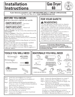
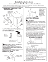
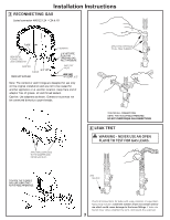
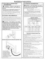
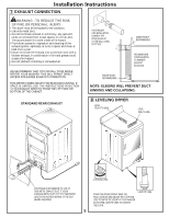
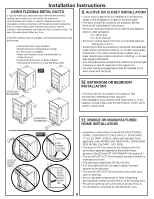
Installation Instructions 5 ELECTRICAL CONNECTION INFORMATION WARNING - TO REDUCE THE RISK OF FIRE, ELECTRICAL SHOCK, AND PERSONAL INJURY: • DO NOT USE AN EXTENSION CORD OR AN ADAPTER PLUG WITH THIS APPLIANCE. Dryer must be electrically grounded in accordance with local codes and ordinances, or in the absence of local codes, in accordance with the NATIONAL ELECTRICAL CODE, ANSI/NFPA NO. 70. ELECTRICAL REQUIREMENTS This appliance must be supplied with 120V, 60Hz, and connected to a properly grounded branch circuit, protected by a 15- or 20amp circuit breaker or time-delay fuse. If electrical supply provided does not meet the above specifications, it is recommended that a licensed electrician install an approved outlet. WARNING - THIS DRYER IS EQUIPPED A THREE-PRONG (GROUNDING) PLUG FOR YOUR PROTECTION AGAINST SHOCK HAZARD AND SHOULD BE PLUGGED DIRECTLY INTO A PROPERLY GROUNDED THREE-PRONG RECEPTACLE. DO NOT CUT OR REMOVE THE GROUNDING PRONG FROM THIS PLUG. 6 EXHAUST INFORMATION WARNING - USE ONLY METAL 4-IN. DUCT. DO NOT USE DUCT LONGER THAN SPECIFIED IN THE EXHAUST LENGTH TABLE. Exhaust longer than specified will: • Increase the drying times and the energy cost. • Reduce the dryer life. • Accumulate lint, creating a potential fire hazard. The correct exhaust installation is your responsibility. Problems due to incorrect installation are not covered by the warranty. The MAXIMUM ALLOWABLE length of the exhaust system depends upon the type of duct, number of turns, the type of exhaust hood (wall cap), and all conditions noted below. Both rigid and flexible metal duct are shown in the table below. EXHAUST LENGTH RECOMEMXEHNDAEUDSMTALXEIMNUGMTLHENGTH RECOMMEExhNaDusEtDHoModATXyIpMeUs M LENGTH Exhaust Recommended Recommended HoUodseTyopnelys for short rUunseinosntalyllafotior nsshort run4"inDIsA.tallations 4" DIA. 4" DIA. 4" DIA. 4" DIA. 4" DIA. No. of 90º NEolb.oowf s90º E0lbows 4" 4" Rigid Metal Rigid 15M0eFtaelet Flexible MFeletxailble 55 FMeeettal Rigid Metal Rigid 125MFeeteatl 2-1/2" Fle2x-1ib/2l"e MFeletaxlible 45 FeMeet tal 10 13950 FFeeeett 525F5eFeteet 11650FFeeeett 42 F4e5eFt eet 21 12650 FFeeeett 494F0eeFteet 10455FFeeeett 39 F3e0eFt eet 32 1415 Feet 483F0eFeteet 9535FeFeetet 35 F2e0eFt eet 43 1035 Feet 432F0eFeteet 8525FeFeetet 33 F1e5eFt eet 5If using fle95xiFbeleet meta4l0dFuecett, plea7se5 Freeefet r to 3p0aFgeee6t . If using flexible metal duct, please refer to page 6. ENSURE PROPER GROUND EXISTS BEFORE USE. EXHAUST SYSTEM CHECK LIST HOOD OR WALL CAP • Terminate in a manner to prevent back drafts or entry of birds or other wildlife. • Termination should present minimal resistance to the exhaust air flow and should require little or no maintenance to prevent clogging. • Never install a screen in or over the exhaust duct. • Wall caps must be installed at least 12 in. above ground level or any other obstruction with the opening pointed down. • If roof vents or louvered plenums are used, they must be equivalent to a 4-in. dampened wall cap in regard to resistance to air flow, prevention of back drafts, and maintenance required to prevent clogging. IF LOCAL CODES PERMIT, AN EXTERNAL GROUND WIRE (NOT PROVIDED), WHICH MEETS LOCAL CODES, MAY BE ADDED BY ATTACHING TO THE GREEN GROUND SCREW ON THE REAR OF THE DRYER, AND TO A GROUNDED METAL COLD WATER PIPE OR OTHER ESTABLISHED GROUND. SEPARATION OF TURNS For best performance, separate all turns by at least 4 ft. of straight duct, including distance between last turn and dampened wall cap. TURNS OTHER THAN 90º • One turn of 45º or less may be ignored. • Two 45º turns should be treated as one 90º turn. • Each turn over 45º should be treated as one 90º turn. SEALING OF JOINTS • All joints should be tight to avoid leaks. The male end of each section of duct must point away from the dryer. • Do not assemble the ductwork with fasteners that extend into the duct. They will serve as a collection point for lint. • Duct joints should be made air-and moisture-tight by wrapping the overlapped joints with duct tape. • Horizontal runs should slope down towards outdoors 1/2 inch per foot. INSULATION • Duct work that runs through an unheated area or is near air conditioning 4 should be insulated to reduce condensation and lint build up.
-
 1
1 -
 2
2 -
 3
3 -
 4
4 -
 5
5 -
 6
6 -
 7
7 -
 8
8
 |
 |
