Hotpoint RB757WHWW User Guide - Page 41
Installation Instructions, INSTALL THE RANGE
 |
View all Hotpoint RB757WHWW manuals
Add to My Manuals
Save this manual to your list of manuals |
Page 41 highlights
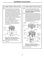
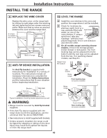
Installation Instructions INSTALL THE RANGE 8 REPLACE THE WIRE COVER Replace the wire cover on the range back by sliding its right edge under the retaining tab and replacing the two screws removed earlier. Make sure that no wires are pinched between the cover and the range back. 2 screws to replace wire cover Retaining tab Wire cover Back of range 9 ANTI-TIP DEVICE INSTALLATION An Anti-Tip bracket is supplied with instructions for installation in a variety of locations. The instructions include all necessary information to complete the installation. Read the Safety Instructions and the instructions that fit your situation before beginning installation. Bracket Screw must enter wood or metal Wall plate Typical installation of anti-tip bracket attachment to wall WARNING: • Range must be secured by Anti-Tip bracket supplied. • If the Anti-Tip device supplied with the range does not fit this application, use the universal Anti-Tip device WB2X7909. • See instructions to install (supplied with bracket). • Unless properly installed, the range could be tipped by stepping or sitting on the door. Injury may result from spilled hot liquids or from the range itself. 10 LEVEL THE RANGE A Install the oven shelves in the oven and position the range where it will be installed. B Check for levelness by placing a spirit level or a cup, partially filled with Spirit level water, on one of the oven shelves. If using a spirit level, take two readings-with the level placed diagonally first in one direction and then the other. C On all models except warming drawer models, remove the storage drawer, broiler drawer or kick panel. The front leveling legs can be adjusted from the bottom and the rear legs can be adjusted from the top. (For warming drawer models, see Step D.) Adjust from the bottom Lower range Leg leveler Raise range Front leveling legs (on some models) Raise range Adjust from the top Lower range Front of range Rear leveling legs (on some models) 40
-
 1
1 -
2
-
3
-
4
-
5
-
6
-
7
-
8
-
9
-
10
-
11
-
12
-
13
-
14
-
15
-
16
-
17
-
18
-
19
-
20
-
21
-
22
-
23
-
24
-
25
-
26
-
27
-
28
-
29
-
30
-
31
-
32
-
33
-
34
-
35
-
 36
36 -
 37
37 -
 38
38 -
 39
39 -
 40
40 -
 41
41 -
 42
42 -
 43
43 -
 44
44 -
 45
45 -
 46
46 -
47
-
48
-
49
-
50
-
51
-
52
-
53
 |
 |
