Hunter 20174 Owner's Manual - Page 7
Setting DIP switches
 |
View all Hunter 20174 manuals
Add to My Manuals
Save this manual to your list of manuals |
Page 7 highlights
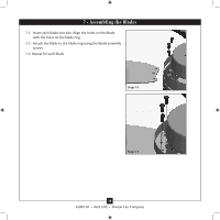
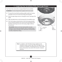
4 • Setting the Remote Transmitter and Receiver Setting DIP switches When two or more fans are located near each other, you may desire to have the receiver/transmitter for each fan set to a different code, so that the operation of one fan does not affect the operation of the other fans. The DIP switches for the receiver are located on the flat surface of the receiver. The DIP switches for the transmitter are in the the battery compartment. Receiver DIP switches 4-1. IMPORTANT! Before you change the DIP switch settings, make sure the battery is not connected to the transmitter. Change the position of the DIP switches in the remote transmitter and the receiver. Make sure that the DIP switches match in the remote receiver and transmitter. If they don't match, the transmitter will not function. 4-2. There is a toggle switch beside the DIP switches on the transmitter. Move the toggle switch toward the side that reads "CFL" if you are going to operate the fan with CFL bulbs. Move the switch to the "INC" side if you are going to use incandescent bulbs. 4-3. Install the included 9-volt battery into the transmitter. CAUTION: The remote control device complies with part 15 of the FCC rules. Changes or modifications not expressly approved by Hunter Fan Company could void your authority to operate this equipment. Operation is subject to the following two conditions: 1. This device may not cause harmful interference. 2. This device must accept any interference received, including interference that may cause undesired operation. WARNING: Use only the Hunter Fan speed control supplied with this fan. INC CFL Transmitter DIP switches Example DIP Switch Settings Receiver 1 Receiver 2 DDIiPp Swwiticthcehses SSeettttoo010111101 Transmitter 1 DDIPip Swwititcchheses SSeett ttoo010010010 Transmitter 2 DDIPipSSwiittcchheses SSeett ttoo001111101 DDIPip Swwititcchheses SSeett ttoo010010010 7 45007-01 • 06/11/09 • Hunter Fan Company
-
 1
1 -
 2
2 -
 3
3 -
 4
4 -
 5
5 -
 6
6 -
 7
7 -
 8
8 -
 9
9 -
 10
10 -
 11
11 -
 12
12 -
13
-
14
-
15
 |
 |
