Hunter 83001 Owner's Manual - Page 18
Install 2 Max 60 watt A-15 bulbs Not Included.
 |
View all Hunter 83001 manuals
Add to My Manuals
Save this manual to your list of manuals |
Page 18 highlights
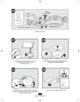
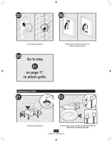
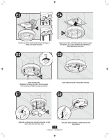
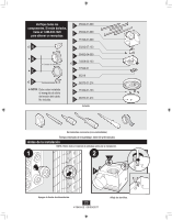
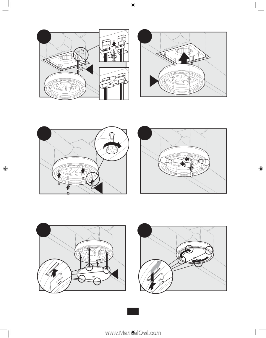
E3 E4 K M Position the strain relief bracket between the plugs as shown, and screw into place. E5 Align posts A, B, C and D (stamped into motor housing) with posts A, B, C and D (stamped into light fixture). Slide light fixture over posts. E6 N Attach thumbscrews. WARNING: To reduce the risk of electrical shock, all 4 thumbscrews MUST be properly installed. E7 Install 2 Max 60 watt A-15 bulbs (Not Included). E8 O Align tabs on glass dome assembly with slots on light fixture, and insert tabs into slots. Turn glass dome assembly as shown until it locks into position. 18 41949-01 09/09/2011
-
 1
1 -
2
-
3
-
4
-
5
-
6
-
7
-
8
-
9
-
10
-
11
-
12
-
 13
13 -
 14
14 -
 15
15 -
 16
16 -
 17
17 -
 18
18 -
 19
19 -
 20
20 -
 21
21 -
 22
22 -
 23
23 -
24
-
25
-
26
-
27
-
28
-
29
-
30
-
31
-
32
-
33
-
34
-
35
-
36
-
37
-
38
-
39
-
40
 |
 |
41949-01
09/09/2011
18
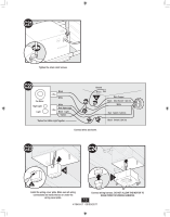
Position the strain relief bracket between the plugs as
shown, and screw into place.
K
E3
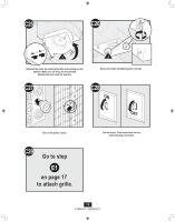
Align tabs on glass dome assembly with slots on light
fixture, and insert tabs into slots.
Install 2 Max 60 watt A-15 bulbs (Not Included).
E8
Turn glass dome assembly as shown until it locks
into position.
E6
O
E7
Attach thumbscrews.
WARNING: To reduce the risk of electrical shock,
all 4 thumbscrews MUST be properly installed.
N
E5
Align posts A, B, C and D (stamped into motor housing)
with posts A, B, C and D (stamped into light fixture).
Slide light fixture over posts.
M
E4