Husqvarna 125B Owners Manual - Page 8
Safety equipment, Stop switch, Muffler, WARNING, Other equipment - will not start
 |
View all Husqvarna 125B manuals
Add to My Manuals
Save this manual to your list of manuals |
Page 8 highlights
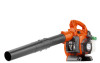
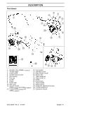
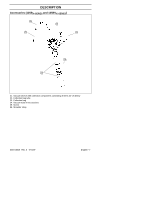
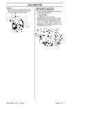
DESCRIPTION Safety equipment The following equipment on the blower is designed for protecting personnel and materials. These components should receive special attention whenever you operate, inspect and service the blower. Other equipment Throttle trigger S The speed and the output of the engine are regulated by the throttle trigger (C). Stop switch S The stop switch (A) is used to stop the engine. A C Variable speed control S The variable speed control (D) is de- signed to allow setting engine speed as necessary during blower use only. Muffler S The muffler is designed to give the lowest possible noise level and to direct the engine's exhaust fumes away from the operator. Mufflers fitted with catalytic converters are also designed to reduce harmful exhaust components. S The engine exhaust fumes are hot and can contain sparks, which may cause fire if they come in contact with dry or flammable material. S Some blower models, especially those sold in countries where the climate is dry, are equipped with a spark arresting screen (B). This screen must be cleaned or replaced at specific intervals. See the Maintenance section. D S To avoid causing damage to the unit, DO NOT attempt to use the variable speed control during starting or during vacuum use. Fan housing S The blower fan housing (E) and the fan impeller (F) provide high performance air discharge. B WARNING: The muffler is ex- tremely hot while the engine is running and after it has stopped. DO NOT TOUCH THE MUFFLER IF IT IS HOT! This can cause severe burns. 545154658 Rev. 2 7/10/07 F E English--- 8
-
 1
1 -
2
-
 3
3 -
 4
4 -
 5
5 -
 6
6 -
 7
7 -
 8
8 -
 9
9 -
 10
10 -
 11
11 -
 12
12 -
 13
13 -
14
-
15
-
16
-
17
-
18
-
19
-
20
-
21
-
22
-
23
-
24
-
25
-
26
-
27
-
28
-
29
-
30
-
31
-
32
-
33
-
34
-
35
-
36
-
37
-
38
-
39
-
40
-
41
-
42
-
43
-
44
-
45
-
46
-
47
 |
 |
