Husqvarna 125B Owners Manual - Page 9
Warning - 125bx
 |
View all Husqvarna 125B manuals
Add to My Manuals
Save this manual to your list of manuals |
Page 9 highlights
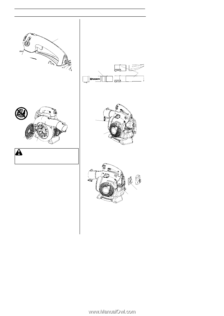
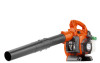
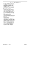
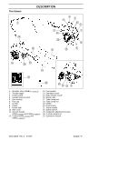
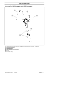
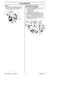
DESCRIPTION Ground wire S The ground wire (G) reduces static build--up during operation in dry conditions. G S The nozzles (L) have a bayonet mount for connection to the blower tube. Air is channeled through the blower tube to the nozzles, where the air discharge velocity increases and the air stream discharge pattern is formed to provide best performance. The length of the blower tube can be adjusted by twisting the nozzle to the left to disengage the bayonet mount and sliding the nozzle to the appropriate position. Twist the nozzle to the right until a click is felt to resecure the nozzle. Inlet cover S An inlet cover (H) is located on the side of the fan housing. Opening this cover allows access for cleaning and inspecting the impeller (125BX--SERIES and 125BVX--SERIES only). If the vacuum tube is used, it must be fitted to the opening in the inlet cover. To open the inlet cover, use a tool to lift the edge of the cover opposite the hinge (indicated by arrow on inlet cover). K L Starter device and starter handle S The starter device (M) is located on the side of the engine shrouding and engages the crankshaft only when the starter handle (N) is pulled. N H J WARNING: Never start the blower if the inlet cover is not closed, is damaged or cannot be closed (except if the vacuum tube is fitted). Cutters (125BX--SERIES and 125BVX--SERIES) S Two cutters (J) are fastened to the impel- ler. The cutters are there to mulch leaves and other debris that have been vacuumed before they enter the collection bag. Blower tube and nozzle NOTE: The tube clamp bolt and nut must be installed prior to initial use (see the general description of the blower on page 6). S The blower tube (K) has a pegged slot mounting system to the unit. To install or remove the blower tube (or collection bag tube for the 125BVX--SERIES), the tube clamp bolt must be removed. Align slot in the blower air outlet with the raised rib on the tube and insert tube until the holes in the tube and housing align. Re--insert the tube clamp bolt and tighten. 545154658 Rev. 2 7/10/07 M Fuel cap S The fuel cap (O) is located at the rear of the engine shrouding on the fuel tank and has a seal to prevent fuel from leaking out. P O Air filter S The air filter (P) consists of a fiber filter medium in a resilient frame. The air filter should be cleaned at specific intervals (see Maintenance section). Otherwise, the blower will consume too much fuel, the performance will be reduced and an oily deposit may form on the spark plug electrodes. English--- 9
-
 1
1 -
2
-
3
-
 4
4 -
 5
5 -
 6
6 -
 7
7 -
 8
8 -
 9
9 -
 10
10 -
 11
11 -
 12
12 -
 13
13 -
 14
14 -
15
-
16
-
17
-
18
-
19
-
20
-
21
-
22
-
23
-
24
-
25
-
26
-
27
-
28
-
29
-
30
-
31
-
32
-
33
-
34
-
35
-
36
-
37
-
38
-
39
-
40
-
41
-
42
-
43
-
44
-
45
-
46
-
47
 |
 |