Husqvarna 1827EXLT Owners Manual - Page 13
To Move Forward And Backward See Fig. 19 - tracks
 |
View all Husqvarna 1827EXLT manuals
Add to My Manuals
Save this manual to your list of manuals |
Page 13 highlights
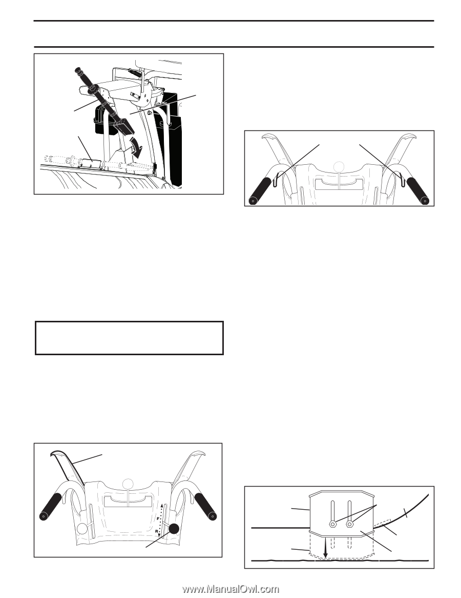
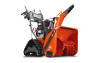
CLEAN-OUT TOOL MOUNTING CLIP OPERATION DISCHARGE CHUTE POWER STEERING OPERATION (See Fig. 20) Steering triggers are used to assist in steering your snow thrower. The triggers are located on the underside of each handle. When a trigger is squeezed, it disengages the track drive on that side of snow thrower and allows it to turn in that direction. • To turn left - squeeze left side trigger. • To turn right - squeeze right side trigger. LH TURN RH TURN TRIGGER TRIGGER FIG. 18 TO MOVE FORWARD AND BACKWARD (See Fig. 19) SELF-PROPELLING, forward and reverse movement of the snow thrower, is controlled by the traction drive control lever located on the left side handle. • Squeeze traction drive control lever to handle to engage the drive system. • Release traction drive control lever to stop the forward or reverse movement of the snow thrower. SPEED and DIRECTION are controlled by the drive speed control lever. • Move speed control lever to desired position AFTER engaging the traction drive control lever. CAUTION: Do not move speed control lever unless engine is running. Damage to the snow thrower can result. • Slower speeds are for heavier snow and faster speeds are for light snow and transporting the snow thrower. It is recommended that you use a slower speed until you are familiar with the operation of the snow thrower. NOTE: When both traction drive and auger control levers are engaged, the traction drive control lever will lock the auger control lever in the engaged position. This will allow you to release your right hand from the handle and adjust the discharge chute direction without interrupting the snow throwing process. TRACTION DRIVE CONTROL LEVER FIG. 20 TO ADJUST SKID PLATES (See Fig. 21) NOTE: The wrench provided in your parts bag may be used to adjust the skid plates. Skid plates are located on each side of the auger housing and adjust the clearance between the scraper bar and the ground surface. Adjust skid plates evenly to proper height for current surface conditions. For removal of snow in normal conditions, such as a paved driveway or sidewalk, place skid plates in the highest position (lowest scraper clearance) to give a 1/8" clearance between the scraper bar and the ground. Use a middle position if the surface to be cleared is uneven. NOTE: It is not recommended to operate the snow thrower over gravel or rocky surfaces. Objects such as gravel, rocks or other debris, can easily be picked up and thrown by the impeller, which can cause serious personal injury, property damage or damage to the snow thrower. • If snow thrower must be operated over gravel surface, use extra caution and be sure skid plates are adjusted to lowest (highest scraper clearance) position. 1. Shut off engine and wait for all moving parts to stop. 2. Adjust skid plates by loosening the hex nuts, then moving skid plate to desired position. Be sure both plates are adjusted evenly. Tighten securely. SCRAPER BAR (See Fig. 21) The scraper bar is not adjustable, but is reversible. After considerable use it may become worn. When it has worn almost to the edge of the housing, it can be reversed, providing additional service before requiring replacement. Replace a damaged or worn scraper bar. DRIVE SPEED CONTROL LEVER FIG. 19 HIGH POSITION (LOW GROUND CLEARANCE) LOW POSITION (HIGH GROUND CLEARANCE) 13 FIG. 21 HEX NUTS AUGER HOUSING SCRAPER BAR SKID PLATE
-
 1
1 -
2
-
3
-
4
-
5
-
6
-
7
-
 8
8 -
 9
9 -
 10
10 -
 11
11 -
 12
12 -
 13
13 -
 14
14 -
 15
15 -
 16
16 -
 17
17 -
 18
18 -
19
-
20
-
21
-
22
-
23
-
24
-
25
-
26
-
27
-
28
 |
 |