Husqvarna MZ54ROPS Owner Manual - Page 16
Fuses, Tracking, Cutting Height Pedal, Hydro Release Levers, IMPORTANT INFORMATION, WARNING
 |
View all Husqvarna MZ54ROPS manuals
Add to My Manuals
Save this manual to your list of manuals |
Page 16 highlights
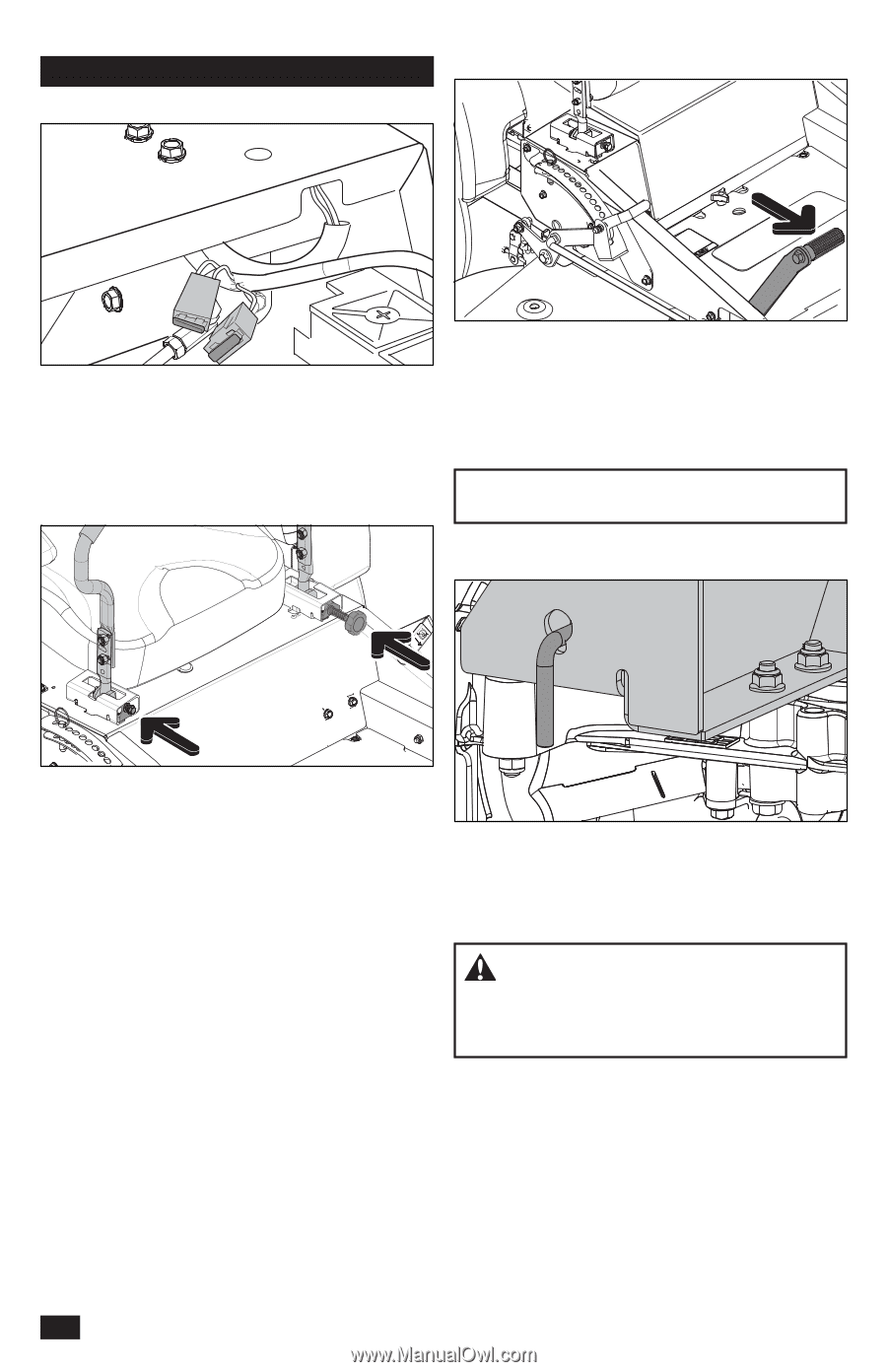
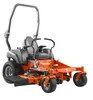
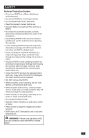
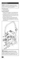
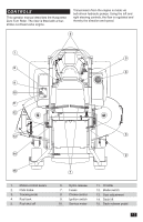
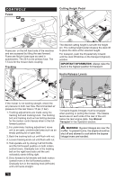
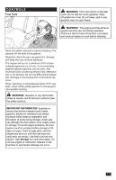
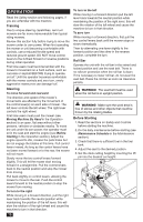
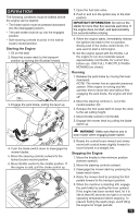
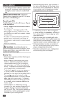
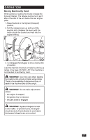
CONTROLS Fuses Cutting Height Pedal Fuses are on the left hand side of the machine and are accessed by tilting the seat forward. Fuses are flat pin fuses type as used in automobiles. The 20 A is the primary fuse. The 7.5 A is for the mower deck coupling. Tracking The desired cutting height is set with the height pin. The cutting height pedal releases the deck lift to place the deck at the selected height. For transport, push the lift pedal fully forward until the deck lift latches in the transport (highest) position. IMPORTANT INFORMATION Always raise the deck to the highest position for transport. Hydro Release Levers If the mower is not tracking straight, check the air pressure in both rear tires. Recommended air pressure for the rear tires is 15 psi (1 bar). 1. Tracking adjustments are made using the tracking bolt and tracking knob. The tracking bolt and tracking knob act as limiting devices for the motion control levers when in the fullforward position. 2. For preliminary tracking adjustment, move unit to an open, unobstructed area such as an empty parking lot or open field. 3. Back the tracking bolt out until flush with nut. 4. Loosen tracking knob out until flush with nut. 5. Test operate unit by driving it at full throttle and the full forward position on both motion control levers. Gradually turn in the tracking bolt on the right hand side until the unit noticeably starts drifting right. 6. Drive forward at full throttle with both motion control levers in the full forward position. Gradually turn in the tracking knob (left side) until unit tracks straight. Transaxle bypass linkages must be engaged when pushing or pulling the mower. The release levers are on each side of the rear of the unit below the rear engine plate. See Manual Transport in the Operation section. WARNING! Bypass linkages are near the muffler. To prevent burns, the engine should be shut off and allowed to cool before the bypass linkage levers are handled. 16
-
 1
1 -
2
-
3
-
4
-
5
-
6
-
7
-
8
-
9
-
10
-
 11
11 -
 12
12 -
 13
13 -
 14
14 -
 15
15 -
 16
16 -
 17
17 -
 18
18 -
 19
19 -
 20
20 -
 21
21 -
22
-
23
-
24
-
25
-
26
-
27
-
28
-
29
-
30
-
31
-
32
-
33
-
34
-
35
-
36
-
37
-
38
-
39
-
40
-
41
-
42
-
43
-
44
-
45
-
46
-
47
-
48
-
49
-
50
-
51
-
52
-
53
-
54
-
55
-
56
-
57
-
58
-
59
-
60
-
61
-
62
-
63
-
64
-
65
-
66
-
67
-
68
-
69
-
70
-
71
-
72
-
73
-
74
-
75
-
76
-
77
-
78
-
79
-
80
 |
 |