Husqvarna Z254i Owners Manual - Page 28
Caster Wheels, Anti-scalp Rollers, V-belts, Deck Belt Removal
 |
View all Husqvarna Z254i manuals
Add to My Manuals
Save this manual to your list of manuals |
Page 28 highlights
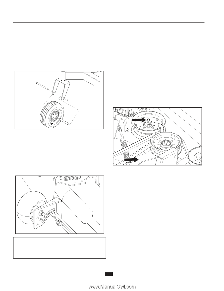
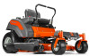
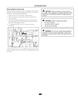
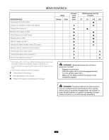
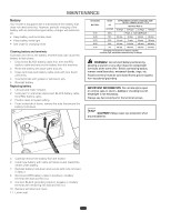
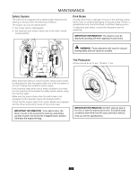
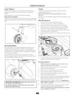
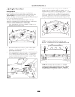
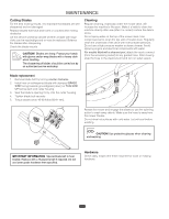
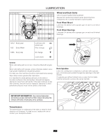
MAINTENANCE Caster Wheels Check every 200 hours. Check that wheels rotate freely. If wheels do not rotate freely take the unit to your dealer for service. Foam filled tires or solid tires will void the warranty. Removal and installation Remove nut and caster bolt. Pull the wheel out of the yoke and take care of the spacers. Install in reverse order. Tighten caster bolt. V-belts Check every 100 hours of operation. Check for severe cracking and large nicks. NOTE: The belt will show some small cracks in normal operation. The belts are not adjustable. Replace belts if they begin to slip from wear. Deck Belt Removal 1. Park on a level surface. Apply park brake. 2. Lower the deck into the lowest cutting position. 3. Remove bolts from belt shields and remove shields. 4. Remove any dirt or grass that may have accumulated around the cutter housings and entire deck surface. 5. Loosen the nut securing the belt guide. Note the position of the belt guide for reinstallation. 6. Push inward on the idler arm to release the tension on the belt. Anti-scalp Rollers Anti-scalp rollers are properly adjusted when they are just slightly off of the ground when the deck is at the desired cutting height in the operating position. Anti-scalp rollers then keep the deck in the proper position to help prevent scalping in most terrain conditions. Anti-scalp rollers can be set in four positions. The rollers should be approximately ¼" (6.5 mm) from the ground. Do not adjust the rollers to support the deck. IMPORTANT INFORMATION Adjust anti-scalp rollers with the mower on a flat level surface. To avoid deck damage, the anti-scalp rollers must not be adjusted to support the deck. 7. Carefully lift the belt over the top of the cutter housing pulleys and remove belt from the deck. Deck Belt Installation NOTE: For ease in installing the deck belt, refer to the routing decal on the top of the deck. 1. Wrap the deck belt around the electric clutch pulley located on the engine shaft. 2. Route the belt forward and up onto the deck. 3. Place belt around spring loaded idler pulley. 4. Wrap the belt around the stationary idler pulley and around the mandrel housings. 5. Push inward on the idler arm and carefully route belt over stationary idler pulley. Once the belt is properly routed, slowly release the idler arm to tension belt. 6. Double check belt routing to make sure it matches the decal affixed to the deck, and the belt does not have any twist. Correct if needed. 7. Tighten the belt guide and replace belt shields on both mandrel housings and secure with fasteners. NOTE: The belt guide should be perpendicular to the belt when installation is complete. 28
-
 1
1 -
2
-
3
-
4
-
5
-
6
-
7
-
8
-
9
-
10
-
11
-
12
-
13
-
14
-
15
-
16
-
17
-
18
-
19
-
20
-
21
-
22
-
 23
23 -
 24
24 -
 25
25 -
 26
26 -
 27
27 -
 28
28 -
 29
29 -
 30
30 -
 31
31 -
 32
32 -
 33
33 -
34
-
35
-
36
-
37
-
38
-
39
-
40
-
41
-
42
-
43
-
44
 |
 |