IBM 71413SU Technical Reference - Page 11
Front and rear layouts, shows the major components at the front of the x3850 M2 and x3950 M2.
 |
UPC - 883436025072
View all IBM 71413SU manuals
Add to My Manuals
Save this manual to your list of manuals |
Page 11 highlights
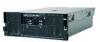
Front and rear layouts Figure 5 shows the major components at the front of the x3850 M2 and x3950 M2. USB connectors DVD-ROM drive Operator information panel 1 2 3 4 Figure 5 Front panel of the x3850 M2 and x3950 M2 Four hot-swap disk drive bays Figure 6 shows the major components at the rear of the server. Gigabit Ethernet 1 Gigabit Ethernet 2 Remote Supervisor Adapter II Power supply 1 System serial SMP Expansion Port 1 SMP Expansion Port 2 SMP Expansion Port 3 Figure 6 Rear panel of the x3850 M2 and x3950 M2 Power supply 2 USB Video connector SAS IBM System x3950 M2 and x3850 M2 Technical Introduction 11
-
 1
1 -
2
-
3
-
4
-
5
-
 6
6 -
 7
7 -
 8
8 -
 9
9 -
 10
10 -
 11
11 -
 12
12 -
 13
13 -
 14
14 -
 15
15 -
 16
16 -
17
-
18
-
19
-
20
-
21
-
22
-
23
-
24
-
25
-
26
-
27
-
28
-
29
-
30
-
31
-
32
-
33
-
34
-
35
-
36
-
37
-
38
-
39
-
40
-
41
-
42
 |
 |

IBM System x3950 M2 and x3850 M2 Technical Introduction
11
Front and rear layouts
Figure 5 shows the major components at the front of the x3850 M2 and x3950 M2.
Figure 5
Front panel of the x3850 M2 and x3950 M2
Figure 6 shows the major components at the rear of the server.
Figure 6
Rear panel of the x3850 M2 and x3950 M2
1
2
3
4
Operator information panel
USB connectors
DVD-ROM drive
Four hot-swap
disk drive bays
Gigabit Ethernet 2
Gigabit Ethernet 1
SMP Expansion Port 1
SMP Expansion Port 2
SMP Expansion Port 3
USB
SAS
System serial
Power
supply 1
Power
supply 2
Remote Supervisor Adapter II
Video connector