IBM 7979BEU User Manual - Page 88
Removing, memory, module, Installing, hot-swap, power, supply
 |
View all IBM 7979BEU manuals
Add to My Manuals
Save this manual to your list of manuals |
Page 88 highlights
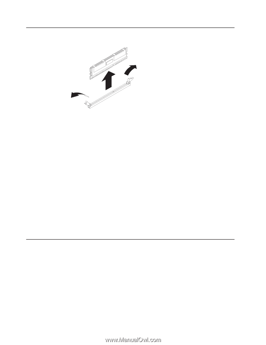
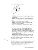
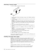
Removing a memory module To remove a DIMM, complete the following steps. 1. Read the safety information that begins on page vii and "Installation guidelines" on page 28. 2. Turn off the server and peripheral devices, and disconnect the power cord and all external cables. Attention: In a dc power environment, only trained service personnel other than IBM service technicians are authorized to connect or disconnect power to the dc power supply. See the documentation that comes with each dc power supply. 3. Remove the cover (see "Removing the cover" on page 31). 4. Remove the riser-card assembly (see "Removing the riser-card assembly" on page 32). 5. Remove the air baffle over the DIMMs (see "Removing the DIMM air baffle" on page 36). Attention: To avoid breaking the retaining clips or damaging the DIMM connectors, open and close the clips gently. 6. Open the retaining clip on each end of the DIMM connector. 7. Lift the DIMM out of the connector. 8. Replace the DIMM or remove the second DIMM of the pair. If you have other optional devices to install or remove, do so now. Otherwise, go to "Completing the installation" on page 81. Installing a hot-swap power supply Attention: The information in this document regarding installing and removing power supplies and connecting and disconnecting power refers to ac power supplies only. If the server contains dc power supplies, see the documentation that comes with the dc power supplies. In a dc power environment, only trained service personnel other than IBM service technicians are authorized to connect or disconnect power to the dc power supply and to install and remove a dc power supply. The server supports a maximum of two hot-swap ac power supplies. Important: Only the configurations that are shown in the following table are supported. The fan numbers are printed on the microprocessor air baffle. 72 System x3650 Type 7979: User's Guide
-
 1
1 -
2
-
3
-
4
-
5
-
6
-
7
-
8
-
9
-
10
-
11
-
12
-
13
-
14
-
15
-
16
-
17
-
18
-
19
-
20
-
21
-
22
-
23
-
24
-
25
-
26
-
27
-
28
-
29
-
30
-
31
-
32
-
33
-
34
-
35
-
36
-
37
-
38
-
39
-
40
-
41
-
42
-
43
-
44
-
45
-
46
-
47
-
48
-
49
-
50
-
51
-
52
-
53
-
54
-
55
-
56
-
57
-
58
-
59
-
60
-
61
-
62
-
63
-
64
-
65
-
66
-
67
-
68
-
69
-
70
-
71
-
72
-
73
-
74
-
75
-
76
-
77
-
78
-
79
-
80
-
81
-
82
-
 83
83 -
 84
84 -
 85
85 -
 86
86 -
 87
87 -
 88
88 -
 89
89 -
 90
90 -
 91
91 -
 92
92 -
 93
93 -
94
-
95
-
96
-
97
-
98
-
99
-
100
-
101
-
102
-
103
-
104
-
105
-
106
-
107
-
108
-
109
-
110
-
111
-
112
-
113
-
114
-
115
-
116
-
117
-
118
-
119
-
120
-
121
-
122
-
123
-
124
-
125
-
126
-
127
-
128
-
129
-
130
-
131
-
132
-
133
-
134
-
135
-
136
-
137
-
138
-
139
-
140
-
141
-
142
-
143
-
144
 |
 |