Icom IC-F1000 Operating Guide - Page 7
LED indicator
 |
View all Icom IC-F1000 manuals
Add to My Manuals
Save this manual to your list of manuals |
Page 7 highlights
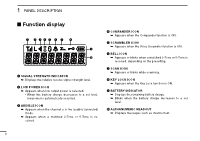
F/S Scan L ow BATT1 R O PANEL DESCRIPTION 1 ■ LED indicator L ow BATT2 OO 1 2 The LED indicator indicates the status of various pTaXraLmowetBerAsToTf1 G G the transceiver as follows: • Receiving 3 (Reference: R=Red, G=Green, O=Orange) T X L ow BATT2 G 4 • Cloning (reading or writing data) • Low Battery 2 (You must charge the battery.) 5 GGGGGGGG G G G G 6 • Cloning Error (if cloning fails) R G R G R G R G R G R G R G R G • Low Battery 1 (You should charge the battery.) G G 7 • Inh, Blank CH, Unlocked (when you cannot use the channel) • When turning ON the power 8 R O R O R O R O R O R O R O R O ROG ROG 9 • TX Low Battery 2 (while transmitting) • Calling 10 N R R R R Clone Err OOO OOO 11 • TX Low Battery 1 (while transmitting) • Audible 12 ink R R Clone TX/RX O O • Transmitting • Lockout, TX Inh, TOT (when transmit is inhibited) 13 R ROOO 14 • Call LED=ON (when receiving a matched 2-Tone or 5-Tone) • Successful 15 T1 O O G 16 • Call LED=Blink (when receiving a matched 2-Tone or 5-Tone) • Failed, Error 2 OO O R • Scanning • Emergency, Siren TT1 G G GOR GOR GOR GOR 4 TT2 G
-
 1
1 -
 2
2 -
 3
3 -
 4
4 -
 5
5 -
 6
6 -
 7
7 -
 8
8 -
 9
9 -
 10
10 -
 11
11 -
 12
12 -
13
-
14
-
15
-
16
-
17
-
18
-
19
-
20
-
21
-
22
-
23
-
24
-
25
-
26
 |
 |
