Image Fitness 3.8 English Manual - Page 12
Nylon Locknut; the Seat Adjustment Bracket must
 |
View all Image Fitness 3.8 manuals
Add to My Manuals
Save this manual to your list of manuals |
Page 12 highlights
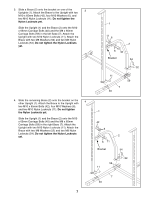
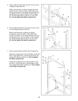
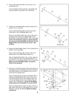
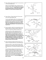
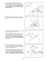
19. Lubricate an M10 x 180mm Bolt (22). Attach the Backrest Tubes (27) to the indicated tube on the 19 Lubricate Bench Frame (5) with the Bolt, two M10 Washers (6), 27 and an M10 Nylon Locknut (11). Note: Do not over- 6 tighten the Nylon Locknut; the Backrest Tubes 22 must pivot easily. 20. Attach the Backrest (15) to the Backrest Tubes (27) 20 with four M6 x 55mm Bolts (4) and four M6 Washers (30). 5 Tube 6 11 15 27 21. Press a 25mm x 50mm Inner Cap (58) into the open end of the Seat Support Tube (37). Lubricate an M8 x 80mm Bolt (9). Attach the Seat Adjustment Bracket (45) to the indicated side of the Seat Support Tube (37) with the Bolt and an M8 Nylon Locknut (54). Note: Do not overtighten the Nylon Locknut; the Seat Adjustment Bracket must pivot easily. 30 30 4 21 9 45 Lubricate 30 4 37 58 54 22. Place the Seat Support Tube (37) on the Bench Frame (5) so that the Seat Adjustment Bracket (45) fits over the welded pin (not visible in the drawing) on the side of the Bench Frame. Lubricate an M10 x 80mm Bolt (56). Attach the Seat Support Tube (37) to the indicated bracket on the Bench Frame (5) with the Bolt and an M10 Nylon Locknut (11). Note: Do not overtighten the Nylon Locknut; the Seat Support Tube must pivot easily. 22 37 45 56 Welded Pin Lubricate 5 11 12
-
 1
1 -
2
-
3
-
4
-
5
-
6
-
 7
7 -
 8
8 -
 9
9 -
 10
10 -
 11
11 -
 12
12 -
 13
13 -
 14
14 -
 15
15 -
 16
16 -
 17
17 -
18
 |
 |
