Image Fitness 833 English Manual - Page 4
Assembly
 |
View all Image Fitness 833 manuals
Add to My Manuals
Save this manual to your list of manuals |
Page 4 highlights
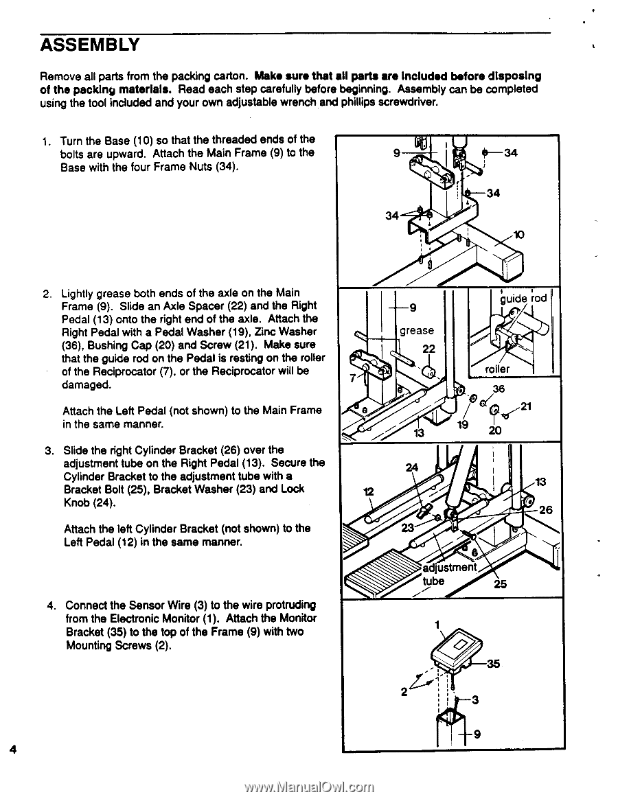
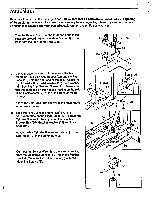
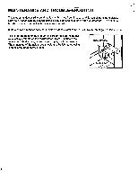
ASSEMBLY Remove all parts from the packing carton. Make sure that all parts are included before disposing of the packing materials. Read each step carefully before beginning. Assembly can be completed using the tool included and your own adjustable wrench and phillips screwdriver. 1. Turn the Base (10) so that the threaded ends of the bolts are upward. Attach the Main Frame (9) to the Base with the four Frame Nuts (34). 9 41 34 8---34 34 10 2. Lightly grease both ends of the axle on the Main Frame (9). Slide an Axle Spacer (22) and the Right Pedal (13) onto the right end of the axle. Attach the Right Pedal with a Pedal Washer (19), Zinc Washer (36), Bushing Cap (20) and Screw (21). Make sure that the guide rod on the Pedal is resting on the roller of the Reciprocator (7), or the Reciprocator will be damaged. Attach the Left Pedal (not shown) to the Main Frame in the same manner. 3. Slide the right Cylinder Bracket (26) over the adjustment tube on the Right Pedal (13). Secure the Cylinder Bracket to the adjustment tube with a Bracket Bolt (25), Bracket Washer (23) and Lock Knob (24). Attach the left Cylinder Bracket (not shown) to the Left Pedal (12) in the same manner. 4. Connect the Sensor Wire (3) to the wire protruding from the Electronic Monitor (1). Attach the Monitor Bracket (35) to the top of the Frame (9) with two Mounting Screws (2). guide rod 9 grease 22 7 roller • 36 ° c( 21 I?f '" 13 20 13 12 26 adjustment . tube 25 1 ' 35 2 .' , 1 3 9 4
-
 1
1 -
 2
2 -
 3
3 -
 4
4 -
 5
5 -
 6
6 -
 7
7 -
 8
8 -
 9
9 -
 10
10 -
11
-
12
 |
 |