Intel 521 Data Sheet - Page 83
Thermal Diode - series
 |
UPC - 683728199029
View all Intel 521 manuals
Add to My Manuals
Save this manual to your list of manuals |
Page 83 highlights
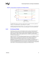
Thermal Specifications and Design Considerations 5.2.7 Thermal Diode The processor incorporates an on-die thermal diode. A thermal sensor located on the system board may monitor the die temperature of the processor for thermal management/long term die temperature change purposes. Table 5-4 and Table 5-5 provide the diode parameter and interface specifications. This thermal diode is separate from the Thermal Monitor's thermal sensor and cannot be used to predict the behavior of the Thermal Monitor. Table 5-4. Thermal Diode Parameters Symbol Parameter Min Typ Max Unit Notes IFW Forward Bias Current n Diode Ideality Factor 11 1.0083 1.011 187 µA 1.023 1 2, 3, 4, 5 RT Series Resistance 3.242 3.33 3.594 Ω 2, 3, 6 NOTES: 1. Intel does not support or recommend operation of the thermal diode under reverse bias. 2. Characterized at 75 °C. 3. Not 100% tested. Specified by design characterization. 4. The ideality factor, n, represents the deviation from ideal diode behavior as exemplified by the diode equation: IFW = IS * (e qVD/nkT -1) where IS = saturation current, q = electronic charge, VD = voltage across the diode, k = Boltzmann Constant, and T = absolute temperature (Kelvin). 5. Devices found to have an ideality factor of 1.0183 to 1.023 will create a temperature error approximately 2 C° higher than the actual temperature. To minimize any potential acoustic impact of this temperature error, TCONTROL will be increased by 2 C° on these parts. 6. The series resistance, RT, is provided to allow for a more accurate measurement of the thermal diode temperature. RT, as defined, includes the pins of the processor but does not include any socket resistance or board trace resistance between the socket and the external remote diode thermal sensor. RT can be used by remote diode thermal sensors with automatic series resistance cancellation to calibrate out this error term. Another application is that a temperature offset can be manually calculated and programmed into an offset register in the remote diode thermal sensors as exemplified by the equation: Terror = [RT * (N-1) * IFWmin] / [nk/q * ln N] where Terror = sensor temperature error, N = sensor current ratio, k = Boltzmann Constant, q = electronic charge. Table 5-5. Thermal Diode Interface Signal Name THERMDA THERMDC Land Number AL1 AK1 § Signal Description diode anode diode cathode Datasheet 83
-
 1
1 -
2
-
3
-
4
-
5
-
6
-
7
-
8
-
9
-
10
-
11
-
12
-
13
-
14
-
15
-
16
-
17
-
18
-
19
-
20
-
21
-
22
-
23
-
24
-
25
-
26
-
27
-
28
-
29
-
30
-
31
-
32
-
33
-
34
-
35
-
36
-
37
-
38
-
39
-
40
-
41
-
42
-
43
-
44
-
45
-
46
-
47
-
48
-
49
-
50
-
51
-
52
-
53
-
54
-
55
-
56
-
57
-
58
-
59
-
60
-
61
-
62
-
63
-
64
-
65
-
66
-
67
-
68
-
69
-
70
-
71
-
72
-
73
-
74
-
75
-
76
-
77
-
 78
78 -
 79
79 -
 80
80 -
 81
81 -
 82
82 -
 83
83 -
 84
84 -
 85
85 -
 86
86 -
 87
87 -
 88
88 -
89
-
90
-
91
-
92
-
93
-
94
-
95
-
96
 |
 |