Intel 630 User Manual - Page 20
Connectors, Headers
 |
UPC - 683728086404
View all Intel 630 manuals
Add to My Manuals
Save this manual to your list of manuals |
Page 20 highlights
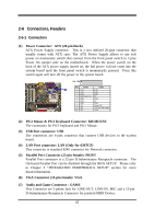
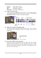
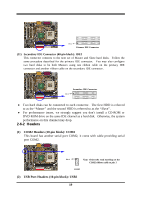
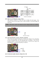
2-6 Connectors, Headers 2-6-1 Connectors (1) Power Connector: ATX (20-pin block) ATX Power Supply connector. This is a new defined 20-pins connector that usually comes with ATX case. The ATX Power Supply allows to use soft power on momentary switch that connect from the front panel switch to 2-pins Power On jumper pole on the motherboard. When the power switch on the back of the ATX power supply turned on, the full power will not come into the system board until the front panel switch is momentarily pressed. Press this switch again will turn off the power to the system board. Pin 1 PIN ROW2 1 3.3V 2 -12V 3 GND 4 Soft Power On 5 GND 6 GND 7 GND 8 -5V 9 +5V 10 +5V ROW1 3.3V 3.3V GND 5V GND 5V GND Power OK +5V (for Soft Logic) +12V (2) PS/2 Mouse & PS/2 Keyboard Connector: KB/MOUSE The connectors for PS/2 keyboard and PS/2 Mouse. (3) USB Port connector: USB The connectors are 4-pins connector that connect USB devices to the system board. (4) LAN Port connector: LAN (Only for 630TCF) This connector is standard RJ45 connector for Network connector. (5) Parallel Port Connector (25-pin female): PRINT Parallel Port connector is a 25-pin D-Subminiature Receptacle connector. The On-board Parallel Port can be disabled through the BIOS SETUP. Please refer to Chapter 3 "INTEGRATED PERIPHERALS SETUP" section for more detail information. (6) VGA Connector (15-pin female): VGA (7) Audio and Game Connector : GAME This Connector are 3 phone Jack for LINE-OUT, LINE-IN, MIC and a 15-pin D-Subminiature Receptacle Connector for joystick/MIDI Device. 17
-
 1
1 -
2
-
3
-
4
-
5
-
6
-
7
-
8
-
9
-
10
-
11
-
12
-
13
-
14
-
 15
15 -
 16
16 -
 17
17 -
 18
18 -
 19
19 -
 20
20 -
 21
21 -
 22
22 -
 23
23 -
 24
24 -
 25
25 -
26
-
27
-
28
-
29
-
30
-
31
-
32
-
33
-
34
-
35
-
36
-
37
-
38
-
39
-
40
-
41
-
42
-
43
-
44
-
45
-
46
-
47
-
48
-
49
-
50
-
51
-
52
-
53
-
54
 |
 |
