Intel BLKD201GLYL Product Specification
Intel BLKD201GLYL Manual
 |
View all Intel BLKD201GLYL manuals
Add to My Manuals
Save this manual to your list of manuals |
Intel BLKD201GLYL manual content summary:
- Intel BLKD201GLYL | Product Specification - Page 1
® Desktop Board D201GLY Technical Product Specification May 2007 Order Number: D88126-001US The Intel® Desktop Board D201GLY may contain design defects or errors known as errata that may cause the product to deviate from published specifications. Current characterized errata - Intel BLKD201GLYL | Product Specification - Page 2
or characteristics of any features or instructions marked "reserved" or "undefined." Intel reserves these for future definition and -421-333, other Countries 708-296-9333. Intel, the Intel logo and Celeron are registered trademarks of Intel Corporation or its subsidiaries in the United States and - Intel BLKD201GLYL | Product Specification - Page 3
connectors, power and environmental requirements, and the BIOS for the Intel® Desktop Board D201GLY. It describes the standard product and available Board D201GLY A map of the resources of the Desktop Board The features supported by the BIOS Setup program A description of the BIOS error messages and - Intel BLKD201GLYL | Product Specification - Page 4
Intel Desktop Board D201GLY Technical Product Specification Other Common Notation # (NxnX) GB GB/sec KB Kbit kbits/sec MB MB/sec Mbit Mbit/sec xxh x.x V * Used - Intel BLKD201GLYL | Product Specification - Page 5
Description 1.1 Overview 10 1.1.1 Feature Summary 10 1.1.2 Manufacturing Options 11 1.1.3 Board Layout 12 1.1.4 Block Diagram 14 1.2 Online Support 15 1.3 Processor 15 1.4 System Memory 16 1.5 Silicon Integrated Systems* Chipset 17 1.5.1 Graphics Subsystem 17 1.5.2 USB 17 1.5.3 IDE - Intel BLKD201GLYL | Product Specification - Page 6
Intel Desktop Board D201GLY Technical Product Specification 2.5 Electrical Considerations 47 2.5.1 DC Autoconfiguration 64 3.3.2 PCI IDE Support 65 3.4 System Management BIOS (SMBIOS 65 3.5 Legacy USB Support 66 3.6 BIOS Updates 66 3.6.1 Language Support 67 3.6.2 Custom Splash Screen - Intel BLKD201GLYL | Product Specification - Page 7
46 12. Localized High Temperature Zones 50 Tables 1. Feature Summary 10 2. Manufacturing Options 11 3. Board Components Shown in Figure 1 13 4. Supported Memory Configurations 16 5. LAN Connector LED States 26 6. Effects of Pressing the Power Switch 28 7. Power States and Targeted System - Intel BLKD201GLYL | Product Specification - Page 8
Intel Desktop Board D201GLY Technical Product Specification 32. Supervisor and User Password Functions 70 33. Front-panel Power LED Blink Codes 71 34. BIOS Error Messages 71 35. Port 80h POST Code Ranges 72 36. Port 80h POST Codes 73 37. Typical Port 80h POST Sequence 76 viii - Intel BLKD201GLYL | Product Specification - Page 9
1 Product Description What This Chapter Contains 1.1 Overview 10 1.2 Online Support 15 1.3 Processor 15 1.4 System Memory 16 1.5 Silicon Integrated Systems* Chipset 17 1.6 S-Video Output 23 1.7 Legacy I/O Controller 23 1.8 Audio Subsystem 24 1.9 LAN Subsystem 26 1.10 Hardware Management - Intel BLKD201GLYL | Product Specification - Page 10
W83627DHG-B I/O controller) Mini-ITX, compatible with microATX (6.75 inches by 6.75 inches [171.45 millimeters by 171.45 millimeters]) Support for the following: • Soldered-down Intel® Celeron® processor with a 533 MHz system bus • One 240-pin DDR2 SDRAM Dual Inline Memory Module (DIMM) socket - Intel BLKD201GLYL | Product Specification - Page 11
every manufacturing option is available in all marketing channels. Please contact your Intel representative to determine which manufacturing options are available to you. Table 2. Manufacturing Options S-Video Output Support for S-Video output. One S-Video output port located on the back panel - Intel BLKD201GLYL | Product Specification - Page 12
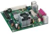
Intel Desktop Board D201GLY Technical Product Specification 1.1.3 Board Layout Figure 1 shows the location of the major components. Figure 1. Board Components Table 3 lists the components identified in Figure 1. 12 - Intel BLKD201GLYL | Product Specification - Page 13
panel audio header Back panel connectors Chassis fan header F +12V power connector (ATX12V) G Main power connector H Intel Celeron processor I DIMM Channel A socket J SiS662 Northbridge K Parallel ATA IDE connector L Front panel I/O header M Battery N SiS964L Southbridge O BIOS - Intel BLKD201GLYL | Product Specification - Page 14
Intel Desktop Board D201GLY Technical Product Specification 1.1.4 Block Diagram Figure 2 is a block diagram of the major functional areas of the board. Figure 2. Block Diagram 14 - Intel BLKD201GLYL | Product Specification - Page 15
" or "Desktop Board Support" http://www.intel.com/design/motherbd http://support.intel.com/support/motherboards/desktop Available configurations for the Desktop http://developer.intel.com/design/motherbd/ly/ly_available.htm Board D201GLY Processor data sheets http://www.intel.com/products/index - Intel BLKD201GLYL | Product Specification - Page 16
Intel Desktop Board D201GLY Technical Product Specification 1.4 System Memory The board has one 240-pin DIMM socket and supports the following memory features: • 1.8 V (only) DDR2 SDRAM DIMMs with gold-plated contacts • Unbuffered, single-sided or double-sided DIMMs with the following restriction: - Intel BLKD201GLYL | Product Specification - Page 17
The board uses the integrated Mirage 1 graphic engine in the SiS662 Northbridge. 1.5.2 USB The board supports up to six USB 2.0 ports, supports UHCI and EHCI, and uses UHCIand EHCI-compatible drivers. The SiS964L Southbridge provides the USB controller for all ports. The port arrangement is as - Intel BLKD201GLYL | Product Specification - Page 18
supports the following modes: • Programmed I/O (PIO): processor controls data transfer. • 8237-style DMA: DMA offloads the processor, supporting transfer supporting host and target throttling and transfer rates of up to 66 MB/sec. ATA-66 protocol is similar to Ultra DMA and is device driver - Intel BLKD201GLYL | Product Specification - Page 19
Product Description 1.5.4 Real-Time Clock, CMOS SRAM, and Battery A coin-cell battery (CR2032) powers the real-time clock and CMOS memory. When the computer is not plugged into a wall socket, the battery has an estimated life of three years. When the computer is plugged in, the standby current from - Intel BLKD201GLYL | Product Specification - Page 20
Intel Desktop Board D201GLY Technical Product Specification VORSICHT Bei falschem Einsetzen einer neuen Batterie besteht Explosionsgefahr. Die Batterie darf nur durch denselben oder einen entsprechenden, vom - Intel BLKD201GLYL | Product Specification - Page 21
Product Description VIGYAZAT Ha a telepet nem a megfelelő típusú telepre cseréli, az felrobbanhat. A telepeket lehetőség szerint újra kell hasznosítani. A használt telepeket a helyi környezetvédelmi előírásoknak megfelelően kell kiselejtezni. AWAS Risiko letupan wujud jika bateri digantikan dengan - Intel BLKD201GLYL | Product Specification - Page 22
Intel Desktop Board D201GLY Technical Product Specification UYARI Yanlış türde pil takıldığında patlama riski vardır. Piller mümkün olduğunda geri dönüştürülmelidir. Kullanılmış piller, yerel çevre yasalarına uygun olarak atılmalıdır. O 22 - Intel BLKD201GLYL | Product Specification - Page 23
options for the I/O controller. 1.7.1 Serial Port The serial port A connector is located on the back panel. The serial port supports data transfers at speeds up to 115.2 kbits/sec with BIOS support. For information about The location of the serial port A connector Refer to Figure 6, page 37 23 - Intel BLKD201GLYL | Product Specification - Page 24
The audio subsystem supports the following audio interfaces: • Front panel audio header, including pins for: ⎯ Line out ⎯ Mic in • Back panel audio connectors: ⎯ Line in ⎯ Line out ⎯ Mic in 1.8.1 Audio Subsystem Software Audio software and drivers are available from Intel's World Wide Web - Intel BLKD201GLYL | Product Specification - Page 25
Product Description 1.8.2 Audio Connectors The board contains audio connectors on the back panel and an audio header on the component side of the board. The front panel audio header is a 2 x 5-pin header that provides mic in and line out signals for front panel audio connectors. The audio subsystem - Intel BLKD201GLYL | Product Specification - Page 26
Intel Desktop Board D201GLY Technical Product Specification 1.9 LAN Subsystem The LAN subsystem consists of . 100 Mbits/sec data rate is selected. 1.9.1 LAN Subsystem Software LAN software and drivers are available from Intel's World Wide Web site. For information about Obtaining LAN software and - Intel BLKD201GLYL | Product Specification - Page 27
diode sensors for direct monitoring of processor temperature and ambient temperature sensing • Fan Monitoring Fan monitoring can be implemented using Intel® Desktop Utilities, LANDesk* software, or third-party support through Advanced Configuration and Power Interface (ACPI) • Hardware support - Intel BLKD201GLYL | Product Specification - Page 28
an operating system that provides full ACPI support. ACPI features include: • Plug and Play (including bus and device enumeration) • Power management control of individual devices, add-in boards (some add-in boards may require an ACPI-aware driver), video displays, and hard disk drives • Methods - Intel BLKD201GLYL | Product Specification - Page 29
Table 7 lists the power states supported by the board along with the 30 W G1 - sleeping state G1 - sleeping state G2/S5 S1 - Processor stopped C1 - stop grant S4 - Suspend to disk. Context saved to external source. No power to the system. Service can be performed safely. Notes: 1. Total - Intel BLKD201GLYL | Product Specification - Page 30
Intel Desktop Board D201GLY Technical Product Specification 1.11.1.2 Wake-up Devices an operating system that provides full ACPI support. In addition, software, drivers, and peripherals must fully support ACPI wake events. 1.11.2 Hardware Support CAUTION Ensure that the power supply provides - Intel BLKD201GLYL | Product Specification - Page 31
). NOTE The use of Resume on Ring and Wake from USB technologies from an ACPI state requires an operating system that provides full ACPI support. 1.11.2.1 Power Connector ATX12V-compliant power supplies can turn off the system power through system control. When an ACPI-enabled system receives the - Intel BLKD201GLYL | Product Specification - Page 32
Intel Desktop Board D201GLY Technical Product Specification 1.11.2.4 Resume on Ring The wakes the computer from ACPI S1 states. NOTE Wake from USB requires the use of a USB peripheral that supports Wake from USB. 1.11.2.6 Wake from PS/2 Devices PS/2 device activity wakes the computer from an ACPI S1 - Intel BLKD201GLYL | Product Specification - Page 33
Product Description 1.11.2.8 +5 V Standby Power Indicator LED The +5 V standby power indicator LED shows that power is still present even when the computer appears to be off. Figure 5 shows the location of the standby power indicator LED. CAUTION If AC power has been switched off and the standby - Intel BLKD201GLYL | Product Specification - Page 34
Intel Desktop Board D201GLY Technical Product Specification 34 - Intel BLKD201GLYL | Product Specification - Page 35
2 Technical Reference What This Chapter Contains 2.1 Memory Map 35 2.2 Connectors and Headers 36 2.3 Jumper Blocks 44 2.4 Mechanical Considerations 46 2.5 Electrical Considerations 47 2.6 Thermal Considerations 49 2.7 Reliability 51 2.8 Environmental 51 2.9 Regulatory Compliance 52 2.1 - Intel BLKD201GLYL | Product Specification - Page 36
Intel Desktop Board D201GLY Technical Product Specification 2.2 Connectors and Headers CAUTION Only the following connectors/headers have overcurrent protection: back panel USB, front panel USB, and - Intel BLKD201GLYL | Product Specification - Page 37
Technical Reference 2.2.1 Back Panel Connectors Figure 6 shows the location of the back panel connectors. The back panel connectors are color-coded. The figure legend (Table 10) lists the colors used (when applicable). Figure 6. Back Panel Connectors Table 10. Back Panel Connectors Shown in Figure - Intel BLKD201GLYL | Product Specification - Page 38
Intel Desktop Board D201GLY Technical Product Specification 2.2.2 Component-side Connectors and Headers Figure 7 shows the locations of the component-side connectors and headers. Figure 7. Component-side - Intel BLKD201GLYL | Product Specification - Page 39
USB header C Front panel USB header D Front panel audio header E Chassis fan header F +12V power connector (ATX12V) G Main power connector H Processor fan header I Parallel ATA IDE connector J Front panel header Table 12. Front Panel Audio Header Pin Signal Name Pin Signal Name - Intel BLKD201GLYL | Product Specification - Page 40
power supply connectors: • Main power - a 2 x 10 connector. The board supports the use of ATX12V power supplies with 2 x 10 or 2 x 12 main power cables. • ATX12V power - a 2 x 2 connector. This connector provides power directly to the processor voltage regulator and must always be used. Failure to - Intel BLKD201GLYL | Product Specification - Page 41
Technical Reference 2.2.2.3 Front Panel Header This section describes the functions of the front panel header. Table 16 lists the signal names of the front panel header. Figure 8 is a connection diagram for the front panel header. Table 16. Front Panel Header Pin Signal In/Out Description Pin - Intel BLKD201GLYL | Product Specification - Page 42
Intel Desktop Board D201GLY Technical Product Specification 2.2.2.3.1 Hard Drive Activity LED Header [Orange] Pins 1 and 3 [Orange] can be connected to an LED to provide a visual indicator - Intel BLKD201GLYL | Product Specification - Page 43
Technical Reference 2.2.3 Front Panel USB Headers Figure 9 is a connection diagram for the front panel USB headers. # INTEGRATOR'S NOTES • The +5 V DC power on the USB connector is fused. • Pins 1, 3, 5, and 7 comprise one USB port. • Pins 2, 4, 6, and 8 comprise one USB port. • Use only a front - Intel BLKD201GLYL | Product Specification - Page 44
Intel Desktop Board D201GLY Technical Product Specification 2.3 Jumper Blocks CAUTION Do not move any jumpers with the power on. Always turn off the power and unplug - Intel BLKD201GLYL | Product Specification - Page 45
than the one described in Table 19. Other jumper configurations are not supported and could damage the Desktop Board. Table 19. Front Panel Audio configuration mode and the computer is powered-up, the BIOS compares the processor version and the microcode version in the BIOS and reports if the - Intel BLKD201GLYL | Product Specification - Page 46
Intel Desktop Board D201GLY Technical Product Specification 2.4 Mechanical Considerations 2.4.1 Form Factor The board is designed to fit into a microATX-form-factor chassis. Figure 11 illustrates the - Intel BLKD201GLYL | Product Specification - Page 47
on the board that is similar to a heavy gaming environment with a 500 mA current draw per USB port. These calculations are not based on specific processor values or memory configurations but are based on the minimum and maximum current draw possible from the board's power delivery subsystems to the - Intel BLKD201GLYL | Product Specification - Page 48
Intel Desktop Board D201GLY Technical Product Specification 2.5.3 Fan Header Current Capability CAUTION The processor fan must be connected to the processor fan header, not to a chassis fan header. Connecting the processor depends on the wake devices supported and manufacturing options. System - Intel BLKD201GLYL | Product Specification - Page 49
remains solely with the reader. Intel makes no warranties or representations that merely following the instructions presented in this document will result Section 2.8. CAUTION Ensure that proper airflow is maintained in the processor voltage regulator circuit. Failure to do so may result in damage - Intel BLKD201GLYL | Product Specification - Page 50
. Maximum case temperatures are important when considering proper airflow to cool the board. For processor case temperature, see processor datasheets and processor specification updates for supported processors. For chipset thermal information, refer to the following website: http:\www.sis.com 50 - Intel BLKD201GLYL | Product Specification - Page 51
shows the MTBF value for each of the D201GLY board's manufacturing options: Table 23. MTBF Values Product Code LAD201GLYT LAD201GLY BOX/BLKD201GLYL LAD201GLYT1 LAD201GLYL1 BOX/BLKD201GLYL1 MTBF Value 327175.8832 hours 327175.8832 hours 339835.5196 hours 327175.8832 hours 327175.8832 hours 339835 - Intel BLKD201GLYL | Product Specification - Page 52
Intel Desktop Board D201GLY Technical Product Specification 2.9 Regulatory Compliance This section contains the following regulatory compliance information for Desktop Board D201GLY: • Safety standards • European Union Declaration - Intel BLKD201GLYL | Product Specification - Page 53
Technical Reference 2.9.2 European Union Declaration of Conformity Statement We, Intel Corporation, declare under our sole responsibility that the product Intel® Desktop Board D201GLY is in conformity with all applicable essential requirements necessary for CE marking, following the provisions of - Intel BLKD201GLYL | Product Specification - Page 54
Intel Desktop Board D201GLY Technical Product Specification Malti Dan il-prodott hu konformi mal-provvedimenti tad-Direttivi Ewropej 2004/108/EC u 2006/95/EC. Norsk Dette - Intel BLKD201GLYL | Product Specification - Page 55
of this program, including the scope of covered products, available locations, shipping instructions, terms and conditions, etc Intel Product Recycling Program http://www.intel.com/intel/other/ehs/product_ecology Deutsch Als Teil von Intels Engagement für den Umweltschutz hat das Unternehmen das - Intel BLKD201GLYL | Product Specification - Page 56
pour en savoir plus sur ce programme, à savoir les produits concernés, les adresses disponibles, les instructions d'expédition, les conditions générales, etc http://www.intel.com/in tel/other/ehs/product_ecology Malay Sebagai sebahagian daripada komitmennya terhadap tanggungjawab persekitaran - Intel BLKD201GLYL | Product Specification - Page 57
Bu programın ürün kapsamı, ürün iade merkezleri, nakliye talimatları, kayıtlar ve şartlar v.s dahil bütün ayrıntılarını ögrenmek için lütfen http://www.intel.com/intel/other/ehs/product_ecology Web sayfasına gidin. 2.9.3.3 Lead Free Desktop Board This Desktop Board is a European Union Restriction of - Intel BLKD201GLYL | Product Specification - Page 58
Intel Desktop Board D201GLY Technical Product Specification Table 26 shows the various forms of the "Lead-Free 2nd Level Interconnect" mark as it appears on the - Intel BLKD201GLYL | Product Specification - Page 59
Technical Reference 2.9.4 EMC Regulations Desktop Board D201GLY complies with the EMC regulations stated in Table 27 when correctly installed in a compatible host system. Table 27. EMC Regulations Regulation Title FCC 47 CFR Part 15, Subpart B Title 47 of the Code of Federal Regulations, Part - Intel BLKD201GLYL | Product Specification - Page 60
Intel Desktop Board D201GLY Technical Product Specification Japanese Kanji statement translation: , it may cause radio interference. Install and use the equipment according to the instruction manual. Korean Class B statement translation: this is household equipment that is certified to comply - Intel BLKD201GLYL | Product Specification - Page 61
: CPU-D201GLY (B) For information about MIC certification, go to http://support.intel.com/support/motherboards/desktop/ Taiwan BSMI (Bureau of Standards, Metrology and Inspections) mark. Includes adjacent Intel company number, D33025. Printed wiring board manufacturer's recognition mark. Consists - Intel BLKD201GLYL | Product Specification - Page 62
Intel Desktop Board D201GLY Technical Product Specification 62 - Intel BLKD201GLYL | Product Specification - Page 63
Speed 68 3.9 BIOS Security Features 70 3.1 Introduction The board uses an Intel BIOS that is stored in the SPI Flash device and can be updated program, POST, the PCI auto-configuration utility, and Plug and Play support. The BIOS displays a message during POST identifying the type of BIOS and - Intel BLKD201GLYL | Product Specification - Page 64
Intel Desktop Board D201GLY Technical Product Specification Table 29 lists the BIOS Setup program menu features. Table 29. BIOS Setup Program Menu Bar Maintenance Main Advanced Security Clears passwords and displays processor information Displays processor and memory configuration Configures - Intel BLKD201GLYL | Product Specification - Page 65
auto-configuration options by specifying manual configuration in the BIOS Setup -66/100/133 operating system device drivers NOTE Do not connect an ATA cache size, and processor speed • Dynamic data, supports an SMBIOS table interface for such operating systems. Using this support, an SMBIOS service - Intel BLKD201GLYL | Product Specification - Page 66
system to prevent accidentally installing an incompatible BIOS. NOTE Review the instructions distributed with the upgrade utility before attempting a BIOS update. For information about BIOS update utilities Refer to http://support.intel.com/support/motherboards/desktop/sb/CS022312.htm. 66 - Intel BLKD201GLYL | Product Specification - Page 67
The BIOS Setup program and help messages are supported in US English. Additional languages are available in the Intel® Integrator Toolkit utility. Check the Intel website for details. 3.6.2 Custom Splash Screen During POST, an Intel® splash screen is displayed by default. This splash screen can - Intel BLKD201GLYL | Product Specification - Page 68
Intel Desktop Board D201GLY Technical Product Specification 3.7.4 Changing the Default Boot Device During POST Pressing the key during POST causes a boot device menu to be - Intel BLKD201GLYL | Product Specification - Page 69
of option ROM boot time. NOTE It is possible to optimize the boot process to the point where the system boots so quickly that the Intel logo screen (or a custom logo splash screen) will not be seen. Monitors and hard disk drives with minimum initialization times can also contribute to a boot - Intel BLKD201GLYL | Product Specification - Page 70
Intel Desktop Board D201GLY Technical Product Specification 3.9 BIOS Security Features The BIOS includes security features that restrict access to the BIOS Setup program and who can - Intel BLKD201GLYL | Product Specification - Page 71
POST, the BIOS causes the front-panel power LED to blink an error message describing the problem (see Table 33). Table 33. Front-panel Power LED Blink Codes Type Pattern Processor initialization complete POST complete BIOS update in progress Video error Memory error Thermal warning On when - Intel BLKD201GLYL | Product Specification - Page 72
Intel Desktop Board D201GLY Technical Product Specification 4.3 Port 80h POST Codes During Ranges Range Category/Subsystem 00 - 0F 10 - 1F Debug codes: Can be used by any PEIM/driver for debug. Host Processors: 1F is an unrecoverable CPU error. 20 - 2F Memory/Chipset: 2F is no memory detected - Intel BLKD201GLYL | Product Specification - Page 73
Codes POST Code Description of POST Operation Host Processor 10 Power-on initialization of the host processor (Boot Strap Processor) 11 Host processor cache initialization (including APs) 12 Starting Application processor initialization 13 SMM initialization Chipset 21 Initializing - Intel BLKD201GLYL | Product Specification - Page 74
Intel Desktop Board D201GLY keyboard 93 Enabling keyboard 94 Clearing keyboard input buffer 95 Instructing keyboard controller to run Self Test (PS/2 only) Mouse BDS Dy Trying boot selection y (y=0 to 15) PEI Core E0 Started dispatching PEIMs (emitted on first report of - Intel BLKD201GLYL | Product Specification - Page 75
(continued) POST Code Description of POST Operation DXE Drivers E7 Waiting for user input E8 Checking password E9 Entering F8 EFI boot service ExitBootServices ( ) has been called F9 EFI runtime service SetVirtualAddressMap ( ) has been called FA EFI runtime service ResetSystem ( ) - Intel BLKD201GLYL | Product Specification - Page 76
Intel Desktop Board D201GLY Technical Product Specification Table 37. Typical Port 80h POST 28 Testing memory 34 Loading recovery capsule E4 Entered DXE phase 12 Starting Application processor initialization 13 SMM initialization 50 Enumerating PCI busses 51 Allocating resources to PCI
-
 1
1 -
 2
2 -
 3
3 -
 4
4 -
 5
5 -
 6
6 -
 7
7 -
8
-
9
-
10
-
11
-
12
-
13
-
14
-
15
-
16
-
17
-
18
-
19
-
20
-
21
-
22
-
23
-
24
-
25
-
26
-
27
-
28
-
29
-
30
-
31
-
32
-
33
-
34
-
35
-
36
-
37
-
38
-
39
-
40
-
41
-
42
-
43
-
44
-
45
-
46
-
47
-
48
-
49
-
50
-
51
-
52
-
53
-
54
-
55
-
56
-
57
-
58
-
59
-
60
-
61
-
62
-
63
-
64
-
65
-
66
-
67
-
68
-
69
-
70
-
71
-
72
-
73
-
74
-
75
-
76
 |
 |

May 2007
Order Number:
D88126-001US
The Intel
®
Desktop Board D201GLY may contain design defects or errors known as errata that may cause the product to deviate from published specifications.
Current
characterized errata are documented in the Intel Desktop Board D201GLY Specification Update.
Intel® Desktop Board
D201GLY
Technical Product Specification