Intel BLKD201GLYL Product Specification - Page 39
Integrator's Note
 |
View all Intel BLKD201GLYL manuals
Add to My Manuals
Save this manual to your list of manuals |
Page 39 highlights
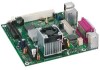
Technical Reference Table 11. Component-side Connectors and Headers Shown in Figure 7 Item/callout from Figure 7 Description A PCI Conventional bus add-in card connector B Front panel USB header C Front panel USB header D Front panel audio header E Chassis fan header F +12V power connector (ATX12V) G Main power connector H Processor fan header I Parallel ATA IDE connector J Front panel header Table 12. Front Panel Audio Header Pin Signal Name Pin Signal Name 1 MIC 3 MIC BIAS 5 FP_OUT_R 7 +5 V 9 FP_OUT_L 2 Ground 4 Ground 6 FP_RETURN_R 8 Key 10 FP_RETURN_L # INTEGRATOR'S NOTE The front panel audio connector is alternately used as a jumper block for routing audio signals. Refer to Section 2.3 on page 44 for more information. Table 13. Chassis Fan Connector Pin Signal Name 1 Control 2 +12 V 3 Tach 39
-
 1
1 -
2
-
3
-
4
-
5
-
6
-
7
-
8
-
9
-
10
-
11
-
12
-
13
-
14
-
15
-
16
-
17
-
18
-
19
-
20
-
21
-
22
-
23
-
24
-
25
-
26
-
27
-
28
-
29
-
30
-
31
-
32
-
33
-
 34
34 -
 35
35 -
 36
36 -
 37
37 -
 38
38 -
 39
39 -
 40
40 -
 41
41 -
 42
42 -
 43
43 -
 44
44 -
45
-
46
-
47
-
48
-
49
-
50
-
51
-
52
-
53
-
54
-
55
-
56
-
57
-
58
-
59
-
60
-
61
-
62
-
63
-
64
-
65
-
66
-
67
-
68
-
69
-
70
-
71
-
72
-
73
-
74
-
75
-
76
 |
 |
