Intel BLKD201GLYL Product Specification - Page 7

s, Tables

Page 7 highlights

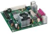
Contents Figures 1. Board Components 12 2. Block Diagram 14 3. Back Panel Audio Connectors 25 4. LAN Connector LED Locations 26 5. Location of the Standby Power Indicator LED 33 6. Back Panel Connectors 37 7. Component-side Connectors and Headers 38 8. Connection Diagram for Front Panel Header 41 9. Connection Diagram for Front Panel USB Headers 43 10. Location of the Jumper Blocks 44 11. Board Dimensions 46 12. Localized High Temperature Zones 50 Tables 1. Feature Summary 10 2. Manufacturing Options 11 3. Board Components Shown in Figure 1 13 4. Supported Memory Configurations 16 5. LAN Connector LED States 26 6. Effects of Pressing the Power Switch 28 7. Power States and Targeted System Power 29 8. Wake-up Devices and Events 30 9. System Memory Map 35 10. Back Panel Connectors Shown in Figure 6 37 11. Component-side Connectors and Headers Shown in Figure 7 39 12. Front Panel Audio Header 39 13. Chassis Fan Connector 39 14. Main Power Connector 40 15. ATX12V Power Connector 40 16. Front Panel Header 41 17. States for a One-Color Power LED 42 18. States for a Two-Color Power LED 42 19. Front Panel Audio Header/Jumper Block 45 20. BIOS Setup Configuration Jumper Settings 45 21. DC Loading Characteristics 47 22. Fan Header Current Capability 48 23. MTBF Values 51 24. Environmental Specifications 51 25. Safety Standards 52 26. Lead-Free Board Markings 58 27. EMC Regulations 59 28. Product Certification Markings 61 29. BIOS Setup Program Menu Bar 64 30. BIOS Setup Program Function Keys 64 31. Boot Device Menu Options 68 vii

  • 1
  • 2
  • 3
  • 4
  • 5
  • 6
  • 7
  • 8
  • 9
  • 10
  • 11
  • 12
  • 13
  • 14
  • 15
  • 16
  • 17
  • 18
  • 19
  • 20
  • 21
  • 22
  • 23
  • 24
  • 25
  • 26
  • 27
  • 28
  • 29
  • 30
  • 31
  • 32
  • 33
  • 34
  • 35
  • 36
  • 37
  • 38
  • 39
  • 40
  • 41
  • 42
  • 43
  • 44
  • 45
  • 46
  • 47
  • 48
  • 49
  • 50
  • 51
  • 52
  • 53
  • 54
  • 55
  • 56
  • 57
  • 58
  • 59
  • 60
  • 61
  • 62
  • 63
  • 64
  • 65
  • 66
  • 67
  • 68
  • 69
  • 70
  • 71
  • 72
  • 73
  • 74
  • 75
  • 76

Contents
vii
Figures
1.
Board Components
..........................................................................
12
2.
Block Diagram
................................................................................
14
3.
Back Panel Audio Connectors
............................................................
25
4.
LAN Connector LED Locations
............................................................
26
5.
Location of the Standby Power Indicator LED
.......................................
33
6.
Back Panel Connectors
.....................................................................
37
7.
Component-side Connectors and Headers
...........................................
38
8.
Connection Diagram for Front Panel Header
........................................
41
9.
Connection Diagram for Front Panel USB Headers
................................
43
10. Location of the Jumper Blocks
...........................................................
44
11. Board Dimensions
...........................................................................
46
12. Localized High Temperature Zones
.....................................................
50
Tables
1.
Feature Summary
............................................................................
10
2.
Manufacturing Options
.....................................................................
11
3.
Board Components Shown in Figure 1
................................................
13
4.
Supported Memory Configurations
.....................................................
16
5.
LAN Connector LED States
................................................................
26
6.
Effects of Pressing the Power Switch
..................................................
28
7.
Power States and Targeted System Power
...........................................
29
8.
Wake-up Devices and Events
............................................................
30
9.
System Memory Map
.......................................................................
35
10.
Back Panel Connectors Shown in Figure 6
...........................................
37
11.
Component-side Connectors and Headers Shown in Figure 7
.................
39
12.
Front Panel Audio Header
.................................................................
39
13.
Chassis Fan Connector
.....................................................................
39
14.
Main Power Connector
......................................................................
40
15.
ATX12V Power Connector
.................................................................
40
16.
Front Panel Header
..........................................................................
41
17.
States for a One-Color Power LED
......................................................
42
18.
States for a Two-Color Power LED
......................................................
42
19.
Front Panel Audio Header/Jumper Block
..............................................
45
20.
BIOS Setup Configuration Jumper Settings
..........................................
45
21.
DC Loading Characteristics
...............................................................
47
22.
Fan Header Current Capability
...........................................................
48
23.
MTBF Values
...................................................................................
51
24.
Environmental Specifications
.............................................................
51
25.
Safety Standards
.............................................................................
52
26.
Lead-Free Board Markings
................................................................
58
27.
EMC Regulations
.............................................................................
59
28.
Product Certification Markings
...........................................................
61
29.
BIOS Setup Program Menu Bar
..........................................................
64
30.
BIOS Setup Program Function Keys
....................................................
64
31.
Boot Device Menu Options
................................................................
68