Intel BOXD845BGSE Product Specification - Page 34
Audio Connectors, Audio Subsystem Software
 |
UPC - 735858150767
View all Intel BOXD845BGSE manuals
Add to My Manuals
Save this manual to your list of manuals |
Page 34 highlights
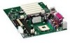
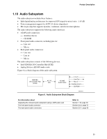
Intel Desktop Board D845BG/D845PT Technical Product Specification 1.10.1 Audio Connectors 1.10.1.1 Front Panel Audio Connector A 2 x 5-pin connector provides mic in and line out signals for front panel audio connectors. For information about Refer to The location of the connector Section 2.8.3, page 71 The signal names of the front panel audio connector Table 40, page 72 Obtaining the Front Panel I/O Connectivity Design Guide Section 1.5, page 19 ✏ NOTE The front panel audio connector is alternately used as a jumper block for routing audio signals. Refer to Section 2.9.1 on page 75 for more information. 1.10.1.2 Auxiliary Line In Connector A 1 x 4-pin ATAPI-style connector connects the left and right channel signals of an internal audio device to the audio subsystem. For information about The location of the auxiliary line in connector The signal names of the auxiliary line in connector Refer to Figure 12, page 59 Table 27, page 60 1.10.1.3 ATAPI CD-ROM Audio Connector A 1 x 4-pin ATAPI-style connector connects an internal ATAPI CD-ROM drive to the audio mixer. For information about The location of the ATAPI CD-ROM connector The signal names of the ATAPI CD-ROM connector Refer to Figure 12, page 59 Table 27, page 60 1.10.2 Audio Subsystem Software Audio software and drivers are available from Intel's World Wide Web site. For information about Obtaining audio software and drivers Refer to Section 1.3, page 18 34
-
 1
1 -
2
-
3
-
4
-
5
-
6
-
7
-
8
-
9
-
10
-
11
-
12
-
13
-
14
-
15
-
16
-
17
-
18
-
19
-
20
-
21
-
22
-
23
-
24
-
25
-
26
-
27
-
28
-
 29
29 -
 30
30 -
 31
31 -
 32
32 -
 33
33 -
 34
34 -
 35
35 -
 36
36 -
 37
37 -
 38
38 -
 39
39 -
40
-
41
-
42
-
43
-
44
-
45
-
46
-
47
-
48
-
49
-
50
-
51
-
52
-
53
-
54
-
55
-
56
-
57
-
58
-
59
-
60
-
61
-
62
-
63
-
64
-
65
-
66
-
67
-
68
-
69
-
70
-
71
-
72
-
73
-
74
-
75
-
76
-
77
-
78
-
79
-
80
-
81
-
82
-
83
-
84
-
85
-
86
-
87
-
88
-
89
-
90
-
91
-
92
-
93
-
94
-
95
-
96
-
97
-
98
-
99
-
100
-
101
-
102
-
103
-
104
-
105
-
106
-
107
-
108
-
109
-
110
-
111
-
112
-
113
-
114
-
115
-
116
-
117
-
118
-
119
-
120
-
121
-
122
-
123
-
124
-
125
-
126
-
127
-
128
-
129
-
130
 |
 |
