Intel D815EEA2U Product Guide - Page 5

Intel D815EEA2U - P3 Socket 370 ATX Motherboard Manual

Page 5 highlights

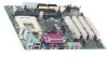
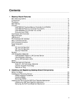
Contents Boot Menu...74 Boot Device Priority Submenu ...75 Hard Disk Drives Submenu ...76 Removable Devices Submenu...76 ATAPI CDROM Drives...77 Exit Menu ...77 5 Technical Reference Desktop Board Connectors ...79 Back Panel Connectors ...80 Midboard Connectors ...81 Front Panel Connectors...85 Desktop Board Resources...86 Interrupts ...86 A Error Messages and Indicators BIOS Beep Codes ...87 BIOS Error Messages ...88 B Regulatory Compliance Safety Regulations ...91 EMC Regulations ...91 Product Certification Markings...92 Installation Precautions ...93 Installation Instructions...93 Ensure Electromagnetic Compatibility (EMC) Compliance ...93 Chassis and Component Certifications ...94 Prevent Power Supply Overload...94 Place Battery Marking ...94 Use Only for Intended Applications...95 Figures 1. 2. 3. 4. 5. 6. 7. 8. 9. 10. 11. 12. 13. 14. 15. D815EEA2 and D815EPEA2 Desktop Board Components...12 D815EFV and D815EPFV Desktop Board Components ...13 Location of Standby Power Indicator (the D815EEA2 Board Is Shown)...24 DIMM Socket Locations (the D815EEA2 Board Is Shown) ...27 Retention Notch Shown on an AGP Card ...28 AGP Connector Location and Retention Mechanism (RM) Placement (Inset) (the D815EEA2 Board Is Shown)...29 Removing the AGP Card Retention Mechanism ...30 Installing and Removing the AGP Card...31 Installing and Removing a GPA Card...32 Installing the I/O Shield ...33 Location of the Mounting Screw Holes for the D815EEA2 and D815EPEA2 Boards ...34 Location of the Mounting Screw Holes for the D815EFV and D815EPFV Boards...35 Installing the Processor in the Processor Socket ...36 Attaching the Heatsink to the Processor ...37 Attaching the Fan Heatsink Clips to the Processor Socket ...37 v

  • 1
  • 2
  • 3
  • 4
  • 5
  • 6
  • 7
  • 8
  • 9
  • 10
  • 11
  • 12
  • 13
  • 14
  • 15
  • 16
  • 17
  • 18
  • 19
  • 20
  • 21
  • 22
  • 23
  • 24
  • 25
  • 26
  • 27
  • 28
  • 29
  • 30
  • 31
  • 32
  • 33
  • 34
  • 35
  • 36
  • 37
  • 38
  • 39
  • 40
  • 41
  • 42
  • 43
  • 44
  • 45
  • 46
  • 47
  • 48
  • 49
  • 50
  • 51
  • 52
  • 53
  • 54
  • 55
  • 56
  • 57
  • 58
  • 59
  • 60
  • 61
  • 62
  • 63
  • 64
  • 65
  • 66
  • 67
  • 68
  • 69
  • 70
  • 71
  • 72
  • 73
  • 74
  • 75
  • 76
  • 77
  • 78
  • 79
  • 80
  • 81
  • 82
  • 83
  • 84
  • 85
  • 86
  • 87
  • 88
  • 89
  • 90
  • 91
  • 92
  • 93
  • 94
  • 95
  • 96

Contents
v
Boot Menu
...........................................................................................................................
74
Boot Device Priority Submenu
....................................................................................
75
Hard Disk Drives Submenu
........................................................................................
76
Removable Devices Submenu
....................................................................................
76
ATAPI CDROM Drives
................................................................................................
77
Exit Menu
............................................................................................................................
77
5
Technical Reference
Desktop Board Connectors
.................................................................................................
79
Back Panel Connectors
..............................................................................................
80
Midboard Connectors
.................................................................................................
81
Front Panel Connectors
..............................................................................................
85
Desktop Board Resources
...................................................................................................
86
Interrupts
....................................................................................................................
86
A
Error Messages and Indicators
BIOS Beep Codes
...............................................................................................................
87
BIOS Error Messages
.........................................................................................................
88
B
Regulatory Compliance
Safety Regulations
..............................................................................................................
91
EMC Regulations
................................................................................................................
91
Product Certification Markings
.............................................................................................
92
Installation Precautions
.......................................................................................................
93
Installation Instructions
........................................................................................................
93
Ensure Electromagnetic Compatibility (EMC) Compliance
.........................................
93
Chassis and Component Certifications
.......................................................................
94
Prevent Power Supply Overload
.................................................................................
94
Place Battery Marking
................................................................................................
94
Use Only for Intended Applications
.............................................................................
95
Figures
1.
D815EEA2 and D815EPEA2 Desktop Board Components
...........................................
12
2.
D815EFV and D815EPFV Desktop Board Components
...............................................
13
3.
Location of Standby Power Indicator (the D815EEA2 Board Is Shown)
........................
24
4.
DIMM Socket Locations (the D815EEA2 Board Is Shown)
...........................................
27
5.
Retention Notch Shown on an AGP Card
.....................................................................
28
6.
AGP Connector Location and Retention Mechanism (RM) Placement (Inset)
(the D815EEA2 Board Is Shown)
..................................................................................
29
7.
Removing the AGP Card Retention Mechanism
...........................................................
30
8.
Installing and Removing the AGP Card
.........................................................................
31
9.
Installing and Removing a GPA Card
............................................................................
32
10. Installing the I/O Shield
.................................................................................................
33
11. Location of the Mounting Screw Holes for the D815EEA2 and D815EPEA2 Boards
....
34
12. Location of the Mounting Screw Holes for the D815EFV and D815EPFV Boards
.........
35
13. Installing the Processor in the Processor Socket
..........................................................
36
14. Attaching the Heatsink to the Processor
.......................................................................
37
15. Attaching the Fan Heatsink Clips to the Processor Socket
...........................................
37